Method for determining the proper operation of a valve in a gas tank system

a gas tank system and valve technology, applied in the direction of machines/engines, electrical control, container discharging methods, etc., can solve the problems of reduced confidence of the driver of the vehicle, reduced safety, and reduced safety of the driver, so as to facilitate the taking of countermeasures and increase confiden

Inactive Publication Date: 2019-05-02
SCANIA CV AB
View PDF0 Cites 4 Cited by
  • Summary
  • Abstract
  • Description
  • Claims
  • Application Information

AI Technical Summary

Benefits of technology

[0010]Thus it is possible to determine whether a valve in the gas tank system operates properly. The method further can be performed on a number of existing gas tank and valve systems. For performing the steps of the method, no extra components are required which are not already present at common gas tank systems. Thus, it is possible to perform the method without the need to exchange or to add components to common gas tank systems. By determining a valve which is not operating properly, negative effects from the non-proper operation of the valve can be avoided, or at least diminished, by performing countermeasures.
[0013]In one example, the first set of gas tank and valve arrangements corresponds to all gas tank and valve arrangements in the gas tank system. This reduces the risk that excess flow valves will perform actions during the time the method is performed. Thus, the results of the method have a higher confidence.
[0014]In one example, the method further comprises the step of determining whether a set of pre-determined conditions is fulfilled. The other steps of the method are only performed once said set of pre-determined conditions is fulfilled. This reduces the risk that other methods performed at the gas tank system or at platforms which carry the gas tank system will interfere in a negative way with the method.
[0015]In one example, the step of determining whether a set of pre-determined conditions is fulfilled is performed intermittently or continuously. The method is aborted when it is determined that said set of pre-determined conditions is not-fulfilled. This reduces the risk that other methods performed at the gas tank system or at platforms which carry the gas tank system will interfere in a negative way with the method.
[0016]In one example, the method further comprises the step of indicating for an operator or a service technician of the gas tank system the valve or valves which have been determined as not properly operating. This highly facilitates taking countermeasures against the non-proper operating valve(s). Examples of countermeasures are replacements or service of the valve(s), and / or a correction of values such as a cruising range of a platform carrying the gas tank system, such as a remaining available amount of fuel, or the like.

Problems solved by technology

However, should a valve fail to open, less fuel would be available for the gas engine.
This can result in that a driver of the vehicle will not be able to drive to a fuel station where he plans to refuel.
Both alternatives can cause considerable costs and loss of time.
At present it is not possible to detect whether a valve fails to open.

Method used


Image

  • Method for determining the proper operation of a valve in a gas tank system
  • Method for determining the proper operation of a valve in a gas tank system
  • Method for determining the proper operation of a valve in a gas tank system

Examples


Embodiment Construction

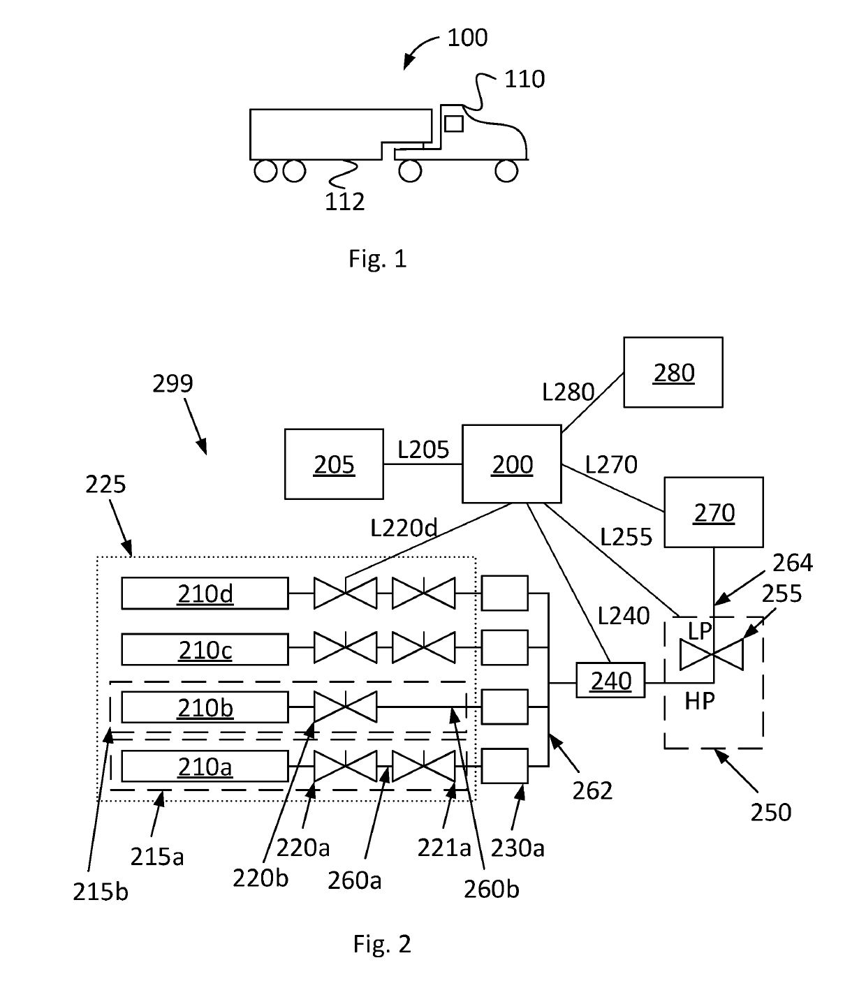
[0035]FIG. 1 shows a side view of a vehicle 100. In the shown example, the vehicle comprises a tractor unit 110 and a trailer unit 112. The vehicle 100 can be a heavy vehicle such as a truck. In one example, no trailer unit is connected to the vehicle 100. The vehicle 100 can comprise a gas engine. The vehicle comprises a gas tank system. The vehicle 100 comprises an engine system 299, see FIG. 2a. The engine system 299 can be arranged in the tractor unit 110.

[0036]In one example, the vehicle 100 is a bus. The vehicle 100 can be any kind of vehicle comprising a gas tank system. Other examples of vehicles comprising a gas tank system are boats, passenger cars, construction vehicles, and locomotives. The present invention can also be used in connection with any other platform than vehicles, as long as this platform comprises a gas tank system. One example is a power plant with a gas tank system.

[0037]The innovative method and the innovative system according to one aspect of the invent...


PUM


Abstract

Disclosed is a method for determining operation of a valve in a gas tank system comprising a plurality of gas tank and valve arrangements, each comprising a gas tank and at least one valve arranged at a passage downstream said gas tank. The method comprises: opening the valves at the passages in a first set of gas tank and valve arrangements; determining a first pressure value at a gas transportation arrangement downstream all of said opened valves; closing the passage at all gas tank and valve arrangements, except for one gas tank and valve arrangement; waiting a pre-determined amount of time; determining a second pressure value at said gas transportation arrangement downstream the gas and tank and valve arrangement whose valve have not been closed; and determining whether said at least one valve which has not been closed operates properly based on said first and second determined pressure values.

Description

CROSS-REFERENCE TO RELATED APPLICATIONS[0001]This application is a national stage application (filed under 35 § U.S.C. 371) of PCT / SE2017 / 050655, filed Jun. 19, 2017 of the same title, which, in turn, claims priority to Swedish Application No. 1650872-3 filed Jun. 21, 2016; the contents of each of which are hereby incorporated by reference.FIELD OF THE INVENTION[0002]The present application relates to a method for determining the proper operation of a valve in a gas tank system. It also relates to a system for determining the proper operation of a valve in a gas tank system, to a computer program and to a computer program product.BACKGROUND OF THE INVENTION[0003]Vehicles with gas engines, especially those which use compressed natural gas, CNG, as fuel, have often several gas bottles as storage tanks. It is often demanded by law that these gas bottles are equipped with valves which close automatically as soon as the engine is turned off. During operation of the gas engine, usually al...

Claims


Application Information

Patent Timeline
Patent Type & Authority Applications(United States)
IPC IPC(8): F02D41/22B60K15/03F02D19/02F02M21/02F17C13/02
CPCF02D41/221B60K15/03006F02D19/023F02M21/0215F02M21/023F17C13/025B60K2015/03026F02D2041/224B60K2015/03013B60Y2200/14B60Y2200/142B60K15/03F02D19/025F02D19/027F02D41/0027F02D41/22F02D2200/0602F02M21/0209F02M21/0224F02M21/0239F02M21/0293F17C13/002F17C2205/0142F17C2205/0326F17C2221/033F17C2223/0123F17C2223/036F17C2250/032F17C2250/036F17C2250/043F17C2260/015F17C2265/066F17C2270/0168Y02T10/30B60K2015/03118F02M21/0242F17C13/02F17C2250/0434
Inventor ECKERDAL, MARTENLOTHGREN, SVANTEJOHANSSON, MAGNUSSUNNEG RDH, ERIK
Owner SCANIA CV AB
Why Eureka
Try Eureka