Dielectric filling member with microwave absorbing element

a filling member and microwave technology, applied in the direction of engine lubrication, liquid/fluent solid measurement, antennas, etc., can solve the problems of large thermal expansion coefficient of suitable materials such as ptfe, high temperature (hpht) applications, and high temperature applications, so as to reduce disturbance and attenuation

Active Publication Date: 2019-05-02
ROSEMOUNT TANK RADAR
View PDF7 Cites 6 Cited by
  • Summary
  • Abstract
  • Description
  • Claims
  • Application Information

AI Technical Summary

Benefits of technology

[0011]It is an object of the present invention to provide an improved way of combining a dielectric filling member with one or several microwave absorbing elements.
[0016]More specifically, by sintering a main body of a polymer material (such as PTFE) with one or several microwave absorbing elements made of a modified polymer (such as modified PTFE), a very reliable integration is achieved. The sintering also eliminates the need for adhesives, and fixates the microwave absorbing element(s) without additional interfaces.
[0022]The microwave absorbing element(s) may serve to reduce resonance in the microwave signals in the wave guiding structure in which the dielectric member is arranged in. If such a microwave absorber is located inside the process seal, and thus subject to the tank atmosphere, it is advantageous to embed the microwave absorbing element(s) in the main body. One example of such an embedded microwave absorber is a pin arranged in the filling member so as to be located close to the opening of the antenna and aligned with the center axis of the antenna. Such embedded microwave absorbers have previously been made of Eccosorb® or even metal, and sealed behind a polymer plug which is glued in place.
[0025]The microwave absorbing element(s) may further serve to avoid interference from a gap between the outside of the filling body and the inside of the wave guiding structure, e.g. an antenna horn. For example, as discussed above, it is known to arrange an attenuating foil around the conical portion of the filling member and fix it with an adhesive.
[0026]According to an embodiment of the present invention, such a conical sleeve can be made of modified polymer, pushing the sleeve onto the outside of the conical portion of the filling member. The sleeve can then be integrated with the main body by sintering. With this approach, there is no longer a risk that the absorbing sleeve becomes detached from the dielectric filling member.

Problems solved by technology

Some applications, known as high-pressure, high temperature (HPHT) applications, present especially challenging conditions.
There are a few challenges with such dielectric filing members.
One potential problem is that suitable materials such as PTFE have large coefficients of thermal expansion, and will expand at elevated temperatures.
This may cause stress, deformation and fatigue in the filling member, and eventually fractures.
Another challenge is that the filing member may cause resonances in the microwave signals.
The combination of a dielectric filling body, made e.g. of PTFE, with one or several microwave absorbing elements may be difficult to manufacture in a reliable manner, without introducing additional interfaces, such as adhesive films or glue.
One specific challenge is that some polymers, such as PTFE, are not liquid when melted.
This means that such materials cannot be injection molded, and also cannot be welded or otherwise joined by melting.

Method used


Image

  • Dielectric filling member with microwave absorbing element
  • Dielectric filling member with microwave absorbing element
  • Dielectric filling member with microwave absorbing element

Examples


Embodiment Construction

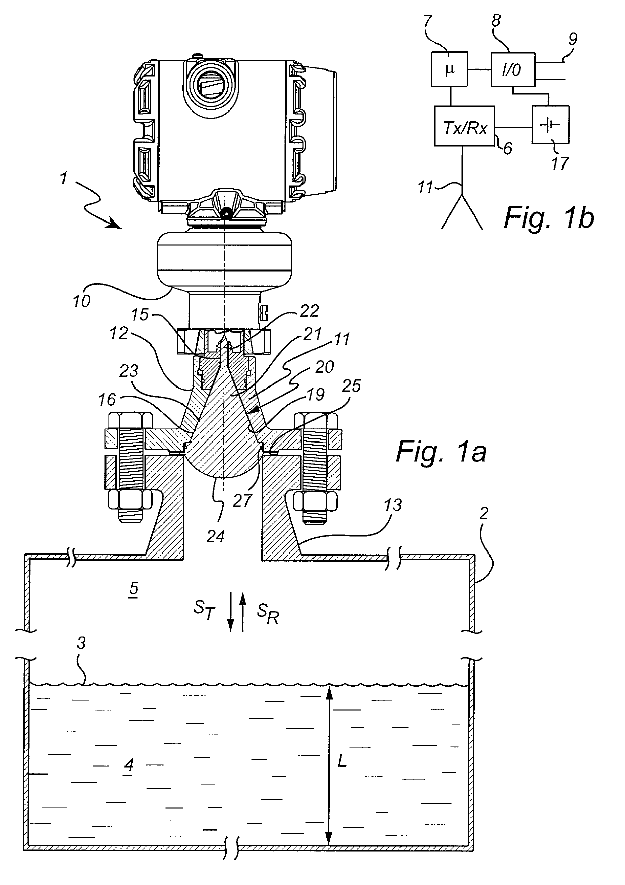
[0035]A radar level gauge (RLG) 1 according to an embodiment of the present invention is illustrated schematically in FIGS. 1a and 1b. The RLG 1 is mounted on a tank 2, and arranged to perform measurements of a process variable such as the level L of an interface between two materials in the tank 2. Typically, the first material is a product 4 stored in the tank, e.g. a liquid such as gasoline, or a solid such as a granular compound, the second material is air or other atmosphere 5 in the tank, while the interface is the surface 3 of the product 4. In some applications, the tank is a very large metal tank (diameter in the order of ten meters).

[0036]The radar level gauge 1 includes transceiver circuitry 6, processing circuitry 7 and an interface 8, illustrated very schematically in FIG. 1. The RLG circuitry, i.e. the transceiver circuitry 6, processing circuitry 7 and a signal / power circuitry 8, is arranged in a measurement unit (MU) 10 mounted to a tank connection 12 made of a metal...


PUM


Abstract

A radar level gauge including a wave guiding structure and a cavity formed inside the wave guiding structure, and a dielectric filling member arranged at least partly within said cavity. The dielectric filling member includes a main body formed of a polymer material, at least one microwave absorbing element formed of a modified polymer material providing a microwave attenuation of at least 1 dB / centimeter at an operating frequency of the radar level gauge, the modified polymer material being obtained by modifying said polymer material with a filler material, wherein the at least one microwave absorbing element is integrally formed with said main body by sintering.

Description

FIELD OF THE INVENTION[0001]The present invention relates to a radar level gauge having a wave guiding structure with a dielectric filling member, which filling member includes a microwave absorbing element. The present invention also related to a method for manufacturing such a dielectric filling member.BACKGROUND OF THE INVENTION[0002]A radar level gauge (RLG) is suitably used for making measurements of a filling level of products such as process fluids, granular compounds and other materials contained in a tank.[0003]An example of such a radar level gauge can include transceiver circuitry for transmitting and receiving microwaves, a signal propagation device arranged to direct microwaves towards the surface and to return microwaves reflected by the surface to the transceiver, and processing circuitry adapted to determine the filling level based on a relation between microwaves transmitted and received by the transceiver.[0004]The signal propagation device may include a wave guidi...

Claims


Application Information

Patent Timeline
Patent Type & Authority Applications(United States)
IPC IPC(8): G01F23/284H01Q13/02
CPCG01F23/284H01Q13/02H01Q13/0283H01Q1/225H01Q19/08
Inventor FREDRIKSSON, HAKANELMBERG, PETEROHLSSON, MAGNUS
Owner ROSEMOUNT TANK RADAR
Why Eureka
Try Eureka