Time of flight camera with photon correlation successive approximation

a time-of-flight camera and photon correlation technology, applied in the field of image sensors for three-dimensional cameras, can solve the problems of large computer processing power, complex technique, and difficulty in creating 3d images using small devices

Active Publication Date: 2019-05-02
OMNIVISION TECH INC
View PDF6 Cites 7 Cited by
  • Summary
  • Abstract
  • Description
  • Claims
  • Application Information

AI Technical Summary

Problems solved by technology

One disadvantage with this triangulation technique is that it is difficult to create 3D images using small devices because there must be a minimum separation distance between each camera in order to create the three dimensional images.
In addition, this technique is complex and therefore requires significant computer processing power in order to create the 3D images in real time.
A continuing challenge wi...

Method used


Image

  • Time of flight camera with photon correlation successive approximation
  • Time of flight camera with photon correlation successive approximation
  • Time of flight camera with photon correlation successive approximation

Examples


Embodiment Construction

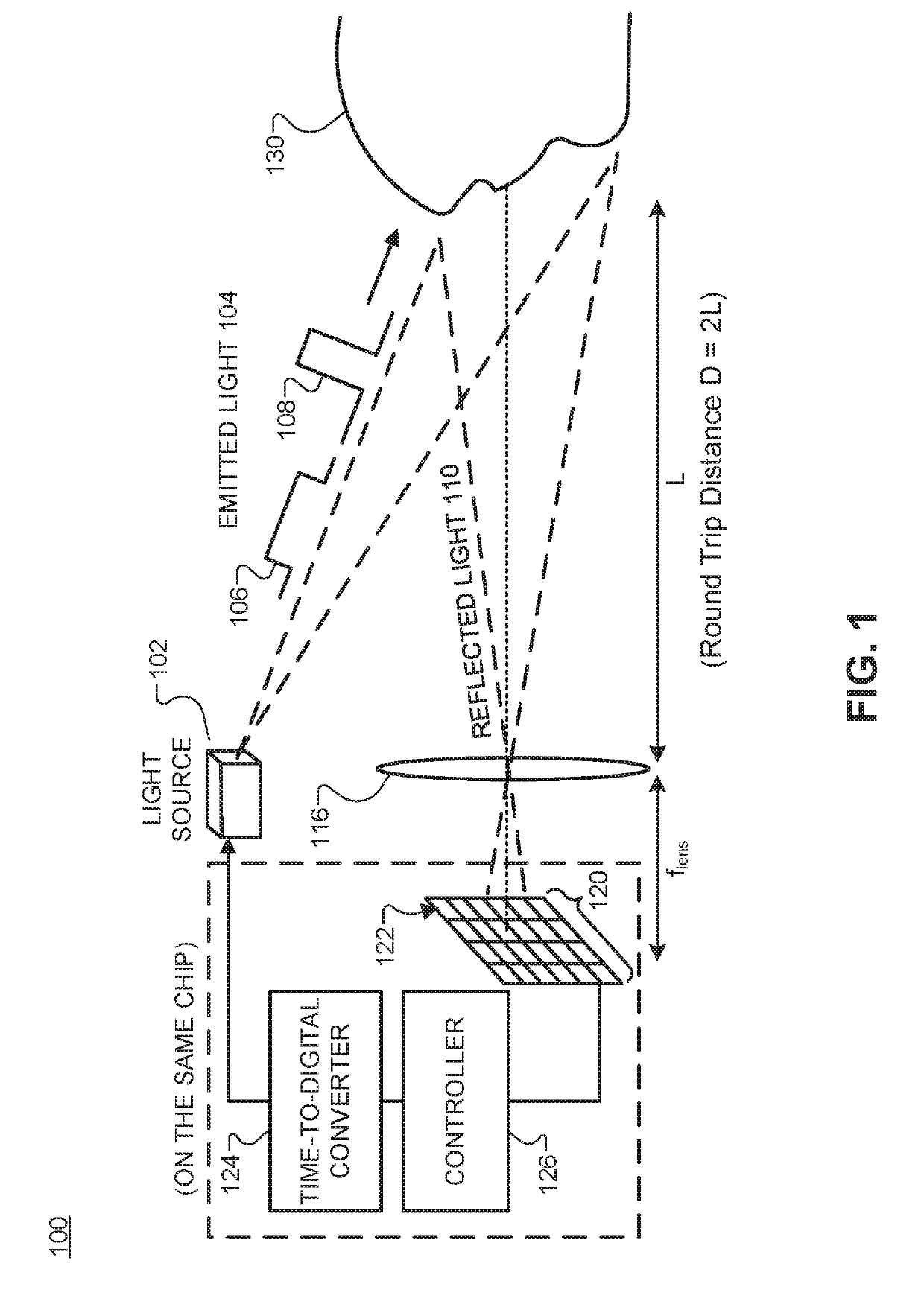
[0012]Examples of an apparatus and method for acquiring time of flight and depth information using a time of flight camera with photon correlation successive approximation are described herein. In the following description, numerous specific details are set forth to provide a thorough understanding of the examples. One skilled in the relevant art will recognize, however, that the techniques described herein can be practiced without one or more of the specific details, or with other methods, components, materials, etc. In other instances, well-known structures, materials, or operations are not shown or described in detail to avoid obscuring certain aspects.

[0013]Reference throughout this specification to “one example” or “one embodiment” means that a particular feature, structure, or characteristic described in connection with the example is included in at least one example of the present invention. Thus, the appearances of the phrases “in one example” or “in one embodiment” in vario...


PUM


Abstract

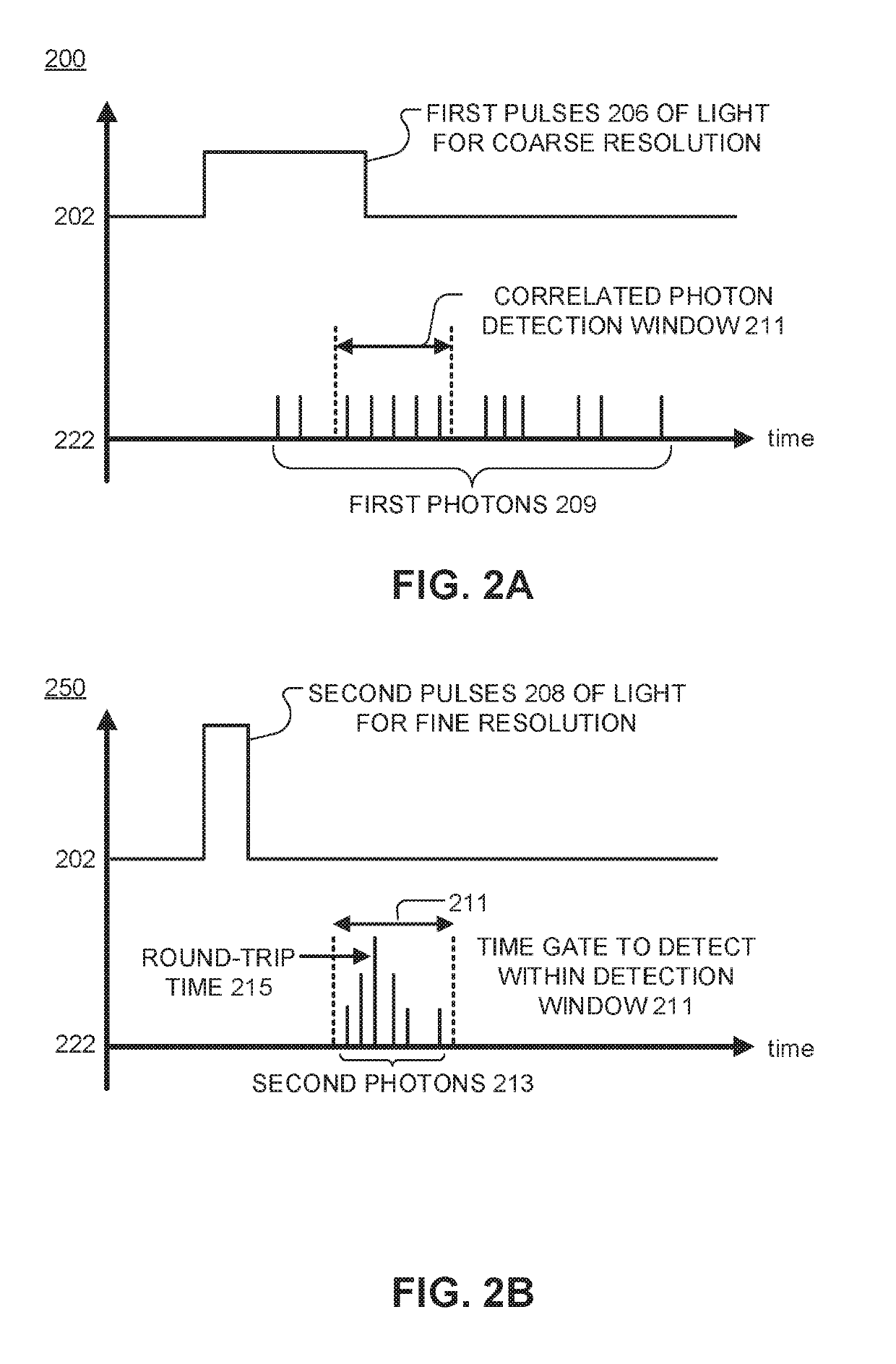
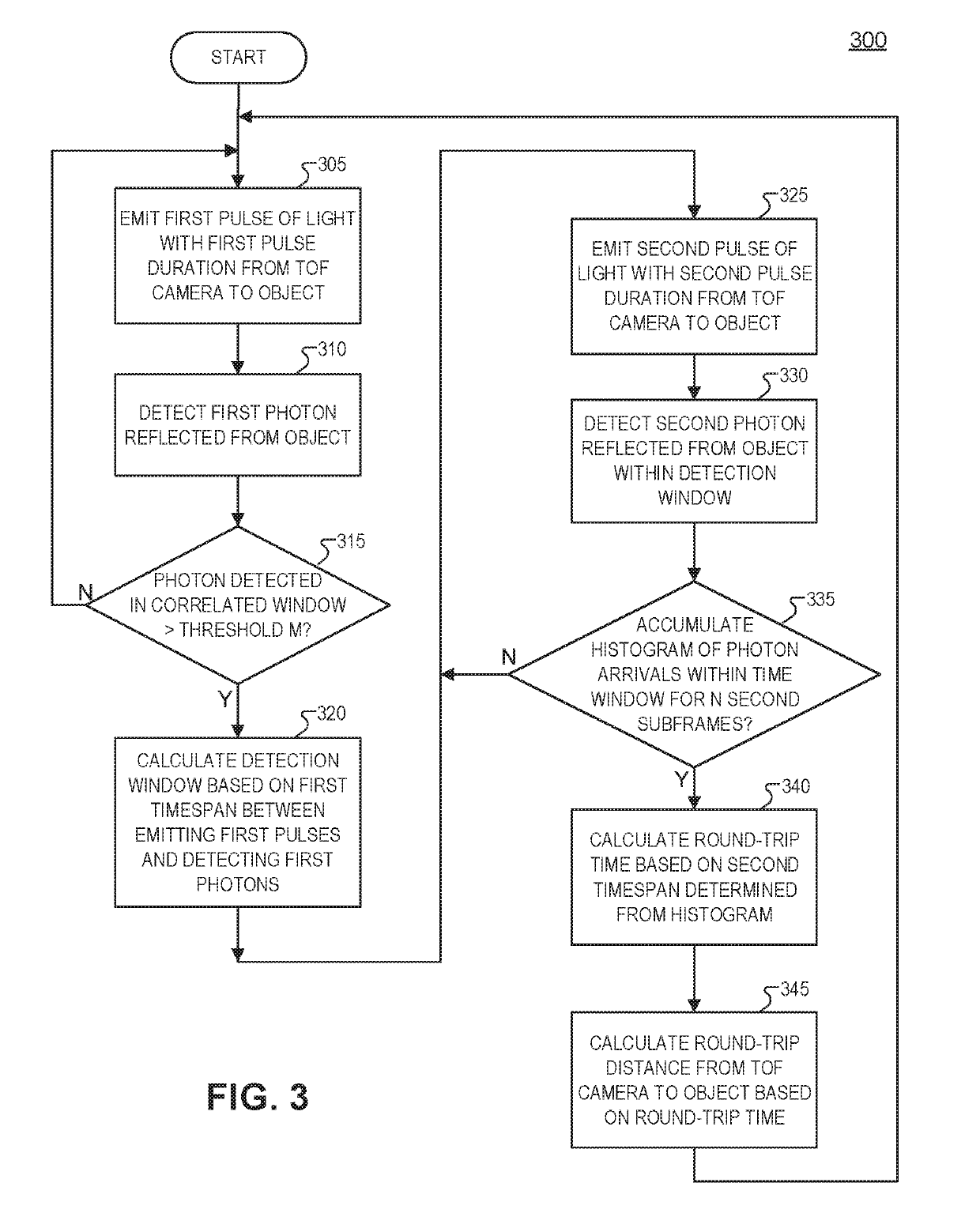
A time of flight camera includes a light source, a first pixel, a time-to-digital converting, and a controller. The light source is configured to emit light towards an object to be reflected back to the time of flight camera as image light. The first pixel includes a photodetector to detect the image light and to convert the image light into an electric signal. The time-to-digital converter is configured to generate timing signals representative of when the light source emits the light and when the photodetector detects the image light. The controller is coupled to the light source, the first pixel, and the time-to-digital converter. The controller includes logic that when executed causes the time of flight camera to perform operations. The operations include determining a detection window for a round-trip time of the image light based, at least in part, on the timing signals and first pulses of the light. The operations also include determining the round-trip time based, at least in part, on the timing signals and second pulses of the light detected within the detection window.

Description

TECHNICAL FIELD[0001]This disclosure relates generally to image sensors. In particular, embodiments of the present invention are related to image sensors for three dimensional cameras.BACKGROUND INFORMATION[0002]Interest in three dimension (3D) cameras is increasing as the popularity of 3D applications continues to grow in areas such as imaging, movies, games, computers, user interfaces, facial recognition, object recognition, augmented reality, and the like. A typical passive way to create 3D images is to use multiple cameras to capture stereo or multiple images. Using the stereo images, objects in the images can be triangulated to create the 3D image. One disadvantage with this triangulation technique is that it is difficult to create 3D images using small devices because there must be a minimum separation distance between each camera in order to create the three dimensional images. In addition, this technique is complex and therefore requires significant computer processing power...

Claims


Application Information

Patent Timeline
IPC IPC(8): H04N5/378G01S17/10G01S7/486G01S17/89H04N5/369G01S7/4865G01S17/894
CPCH04N5/378G01S17/10G01S7/4865G01S17/89H04N5/3696G06T7/521G01S17/894H04N25/75H04N25/702
Inventor WEBSTER, ERIC A. G.
Owner OMNIVISION TECH INC
Why Eureka
Try Eureka