Space based magnetic vortex accelerator and methods of use thereof

a space-based, accelerator technology, applied in the direction of magnet bodies, generators/motors, machines/engines, etc., can solve the problems of limited spacecraft performance, limited launch time, cooling requirements, etc., to maintain the super conductivity of the storage ring and the series of electromagnetic coils

Active Publication Date: 2019-05-09
WEST BRANDON
View PDF0 Cites 4 Cited by
  • Summary
  • Abstract
  • Description
  • Claims
  • Application Information

AI Technical Summary

Benefits of technology

[0008]Briefly described, in an example embodiment, the present disclosure overcomes the above-mentioned disadvantages and meets the recognized need for a space based magnetic vortex accelerator and methods of use thereof, that generally includes one or more sections of magnetic material configured as a conduit with a flightpath therethrough for the spacecraft, a magnetic coil field generator electrically connected to said one or more sections of magnetic material configured to generate a space based magnetic field via said one or more sections of magnetic material, a power plant electrically connected to said magnetic coil field generator, said power plant configured to power said magnetic coil field generator, one or more magnetic field receivers affixed to the spacecraft, said one or more magnetic field receivers configured to magnetically engage said space based magnetic field.

Problems solved by technology

Chemically-fueled rockets require that fuel be brought along, and this limits the performance of the spacecraft.
These launches are limited to the timing, position, distance, and final destination of the projectile in relation to the concentrated mass used as a launch.
Some disadvantages to this approach include the requirement of extreme velocities necessary to achieve escape velocity of planet earth, and the cooling requirements to maintain super conductivity of the storage ring and the series of electromagnetic coils.
One disadvantage of this approach is that the space craft does not participate in amplifying the magnitude of the force in the electromagnetic propulsion function.

Method used


Image

  • Space based magnetic vortex accelerator and methods of use thereof
  • Space based magnetic vortex accelerator and methods of use thereof
  • Space based magnetic vortex accelerator and methods of use thereof

Examples


Embodiment Construction

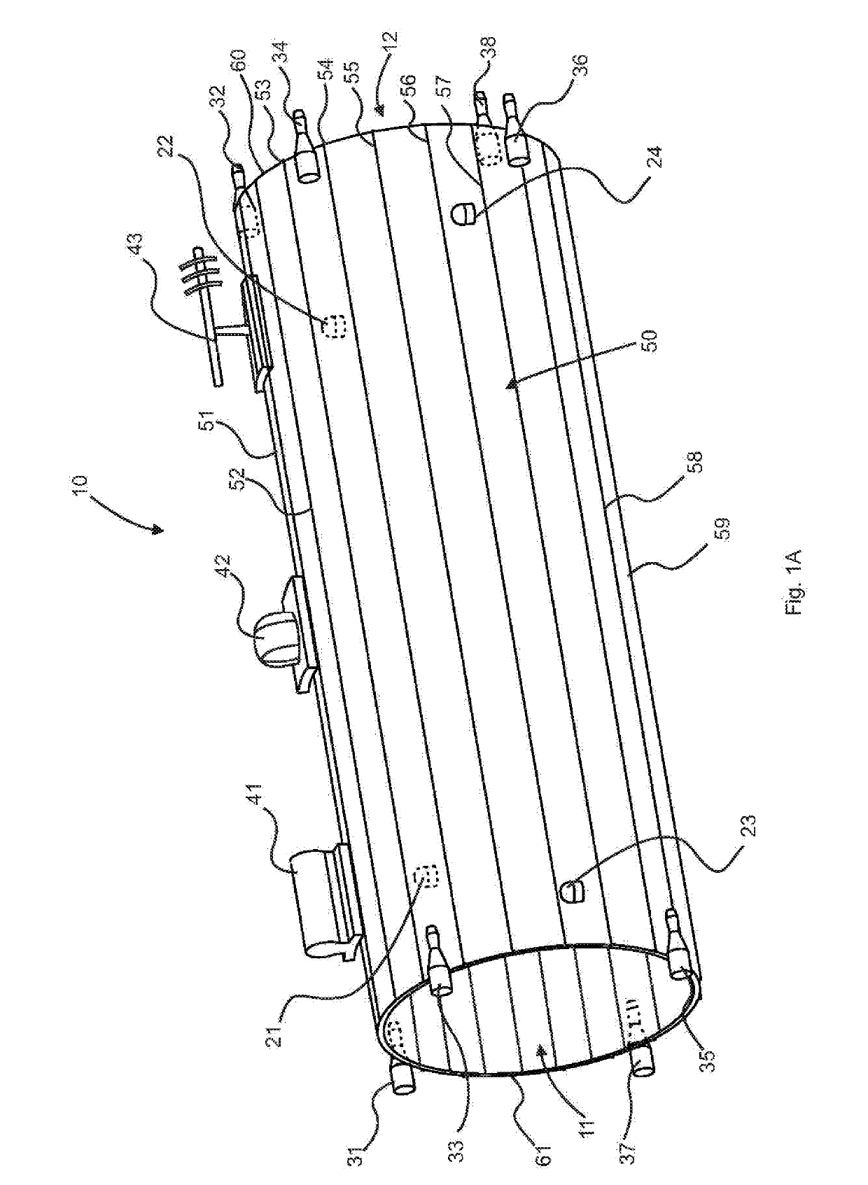
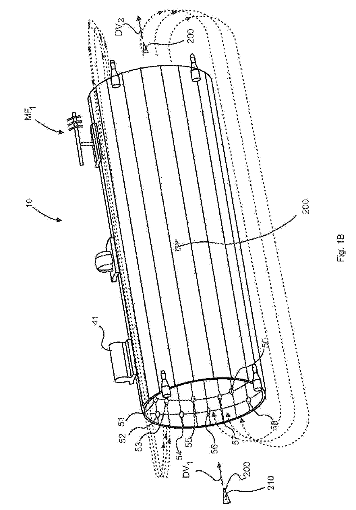
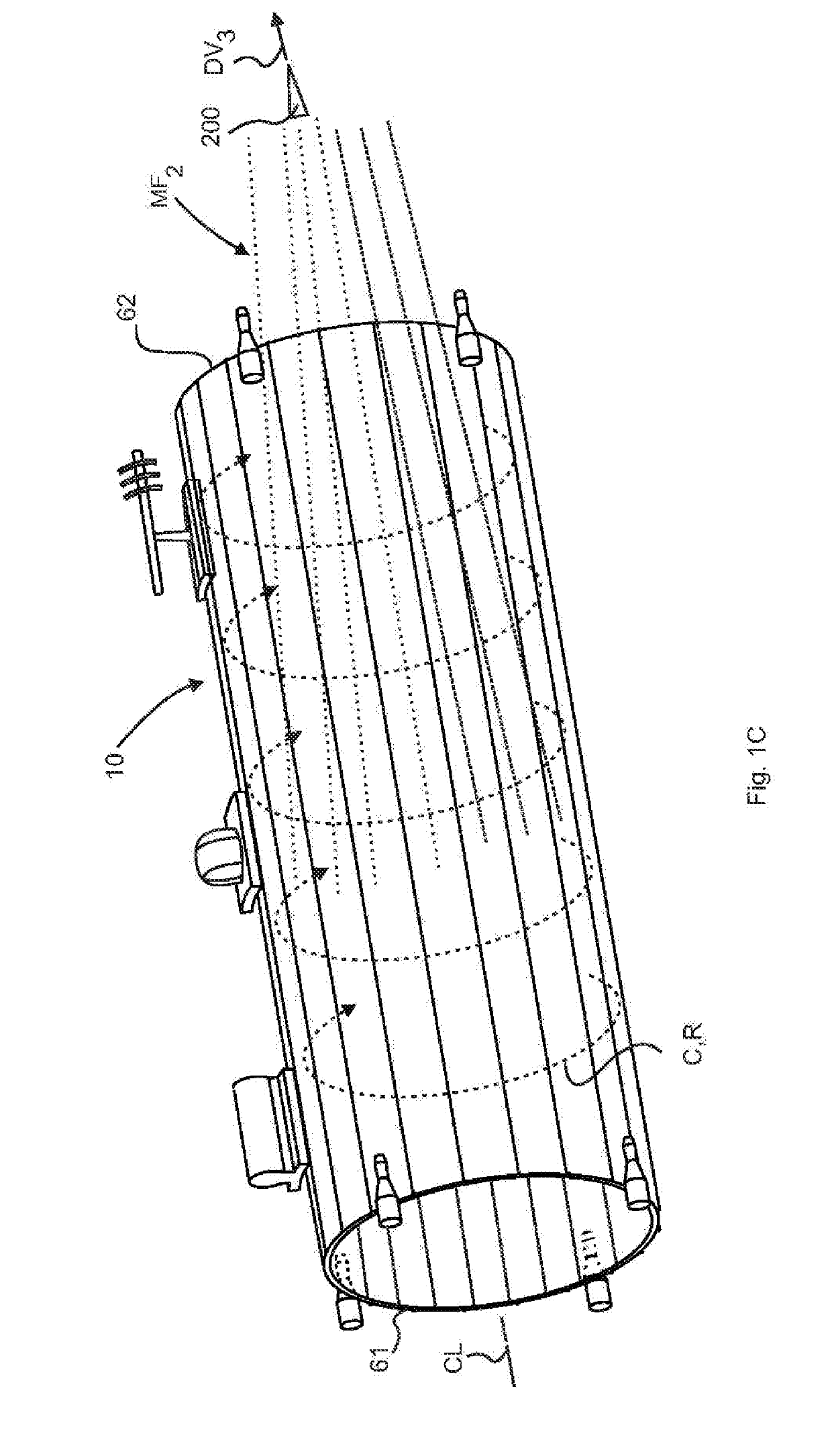
[0038]In describing the exemplary embodiments of the present disclosure, as illustrated in FIGS. 1A, 1B, 1C, 2A, 2B, 3, 4A, 4B, and 5 specific terminology is employed for the sake of clarity. The present disclosure, however, is not intended to be limited to the specific terminology so selected, and it is to be understood that each specific element includes all technical equivalents that operate in a similar manner to accomplish similar functions. Embodiments of the claims may, however, be embodied in many different forms and should not be construed to be limited to the embodiments set forth herein. The examples set forth herein are non-limiting examples, and are merely examples among other possible examples.

[0039]Referring now to FIGS. 1A, 1B and 1C, by way of example, and not limitation, there is illustrated an example embodiment space based magnetic vortex accelerator system 10. Space based magnetic vortex accelerator system 10 may be configured having one or more magnetic coils, ...


PUM


Abstract

A space based magnetic vortex accelerator and methods of use thereof having one or more sections of magnetic material configured as a conduit with a flightpath therethrough for the spacecraft, a magnetic coil field generator electrically connected to said one or more sections of magnetic material configured to generate a space based magnetic field via said one or more sections of magnetic material, a power plant electrically connected to said magnetic coil field generator, said power plant configured to power said magnetic coil field generator, one or more magnetic field receivers affixed to the spacecraft, said one or more magnetic field receivers configured to magnetically engage said space based magnetic field.

Description

CROSS-REFERENCE TO RELATED APPLICATIONS[0001]To the full extent permitted by law, the present application hereby claims priority to and the full benefit of U.S. Provisional Application No. 62 / 544,766, filed on Aug. 11, 2017, entitled “SPACE BASED ACCELERATOR AND METHODS OF USE THEREOF,” which is incorporated herein by reference in its entirety.TECHNICAL FIELD[0002]This disclosure relates to rocketry or spacecraft accelerator system and methods of use thereof. More specifically the disclosure relates to an accelerator to accelerate a spacecraft in zero or low-gravity environment using electromagnetic forces.BACKGROUND[0003]The current state of the art in spacecraft propulsion utilizes a variety of chemical fuels, either liquid, gas, or solid fuel. Chemically-fueled rockets require that fuel be brought along, and this limits the performance of the spacecraft.[0004]Moreover, space launches utilize parabolic path and hyperbolic path trajectories around concentrated masses, such as stars...

Claims


Application Information

Patent Timeline
Patent Type & Authority Applications(United States)
IPC IPC(8): B64G1/40H02N11/00
CPCB64G1/409H02N11/006H01F7/202B64G1/422F03H1/0081B64G1/2427
Inventor WEST, BRANDON
Owner WEST BRANDON
Why Eureka
Try Eureka