Test object visualizing device

Active Publication Date: 2019-05-09
SAITAMA MEDICAL UNIVERSITY
View PDF3 Cites 1 Cited by
  • Summary
  • Abstract
  • Description
  • Claims
  • Application Information

AI Technical Summary

Benefits of technology

[0031]The present invention can solve the problems in the related art and provide a test object visualizing device capable of simultaneously capturing a molecule distribution image and a tomographic image of a test object.

Problems solved by technology

However, because it is impossible to also judge the time when a disease will occur, it is important to discover the occurrence of a disease in a less invasive manner in an early stage of the disease and realize a less invasive treatment.

Method used


Image

  • Test object visualizing device
  • Test object visualizing device
  • Test object visualizing device

Examples


examples

[0085]The present invention will be described below by way of Examples. The present invention should not be construed as being limited to these Examples.

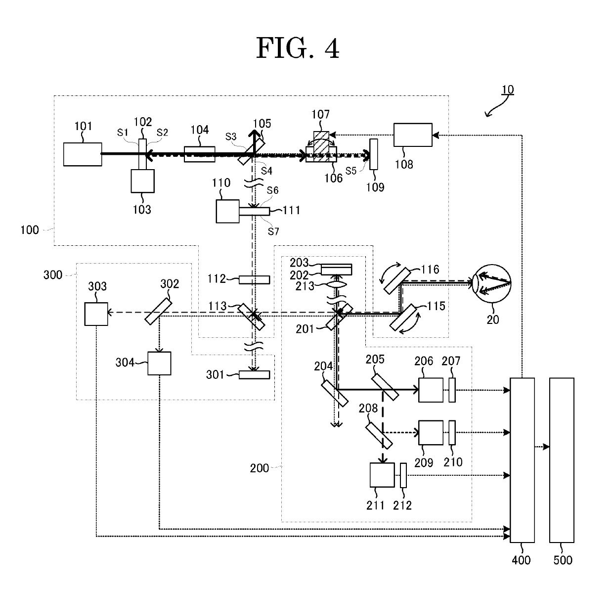
[0086]FIG. 4 is a diagram illustrating a test object visualizing device according to an Example.

[0087]As illustrated in FIG. 4, a test object visualizing device 10 includes a light irradiating unit 100, a molecule distribution image generating unit 200, a tomographic image generating unit 300, a signal processing unit 400, and an image display unit 500.

[0088]A fundamental wave laser 101 of the light irradiating unit 100 is configured to emit a laser beam having a wavelength of 1,064 nm to a dichroic mirror 102. The laser beam is a mode-locked laser beam with which a picosecond or femtosecond mode is synchronized.

[0089]The dichroic mirror 102 has a non-reflection property to light having a wavelength of 1,064 nm on its S1 surface. The dichroic mirror 102 has a non-reflection property to light having a wavelength of 1,064 nm and a tot...


PUM

PropertyMeasurementUnit
wavelengthaaaaaaaaaa
Stokes light wavelengthaaaaaaaaaa

Abstract

Provided is a test object visualizing device, including: light irradiating unit configured to make wavelength of at least any one of pump light and Stokes light generated on the same optical path variable per test position of test object, and irradiate test object with pump light and Stokes light; molecule distribution image generating unit configured to detect anti-Stokes light emitted from test object according to wavelength difference between pump light and Stokes light, and generate a molecule distribution image based on anti-Stokes light; tomographic image generating unit configured to detect at least any one of reflected light from test object when irradiated with pump light and reflected light from test object when irradiated with Stokes light, and generate a tomographic image of test object based on the reflected light detected; and image display unit configured to display at least any one of molecule distribution image and tomographic image generated.

Description

TECHNICAL FIELD[0001]The present invention relates to a test object visualizing device configured to visualize a molecule distribution image and a cross-section of a test object.BACKGROUND ART[0002]In recent years, the genetic diagnosis has made a remarkable progress and brought about an era in which it is possible to judge what disease risks individuals genetically have or not. However, because it is impossible to also judge the time when a disease will occur, it is important to discover the occurrence of a disease in a less invasive manner in an early stage of the disease and realize a less invasive treatment.[0003]For discovery of a disease in its early stage, it is important to identify a functional change of a test object at a previous stage before the test object undergoes a morphological change. In order to identify a functional change, molecule distribution imaging techniques capable of visualizing the distribution of the molecules of, for example, a specific protein in a ce...

Claims


Application Information

Patent Timeline
Patent Type & Authority Applications(United States)
IPC IPC(8): G01N21/65A61B5/00
CPCG01N21/65A61B5/0066G01N2021/653A61B3/102A61B3/18A61B5/14507A61B5/4881G02F1/39H01S3/0092A61B3/10
Inventor TOIDA, MASAHIRO
Owner SAITAMA MEDICAL UNIVERSITY
Why Eureka
Try Eureka