
Power terminal and motor including same

Active Publication Date: 2019-05-09
LG INNOTEK CO LTD
View PDF0 Cites 1 Cited by
  • Summary
  • Abstract
  • Description
  • Claims
  • Application Information

AI Technical Summary

Benefits of technology

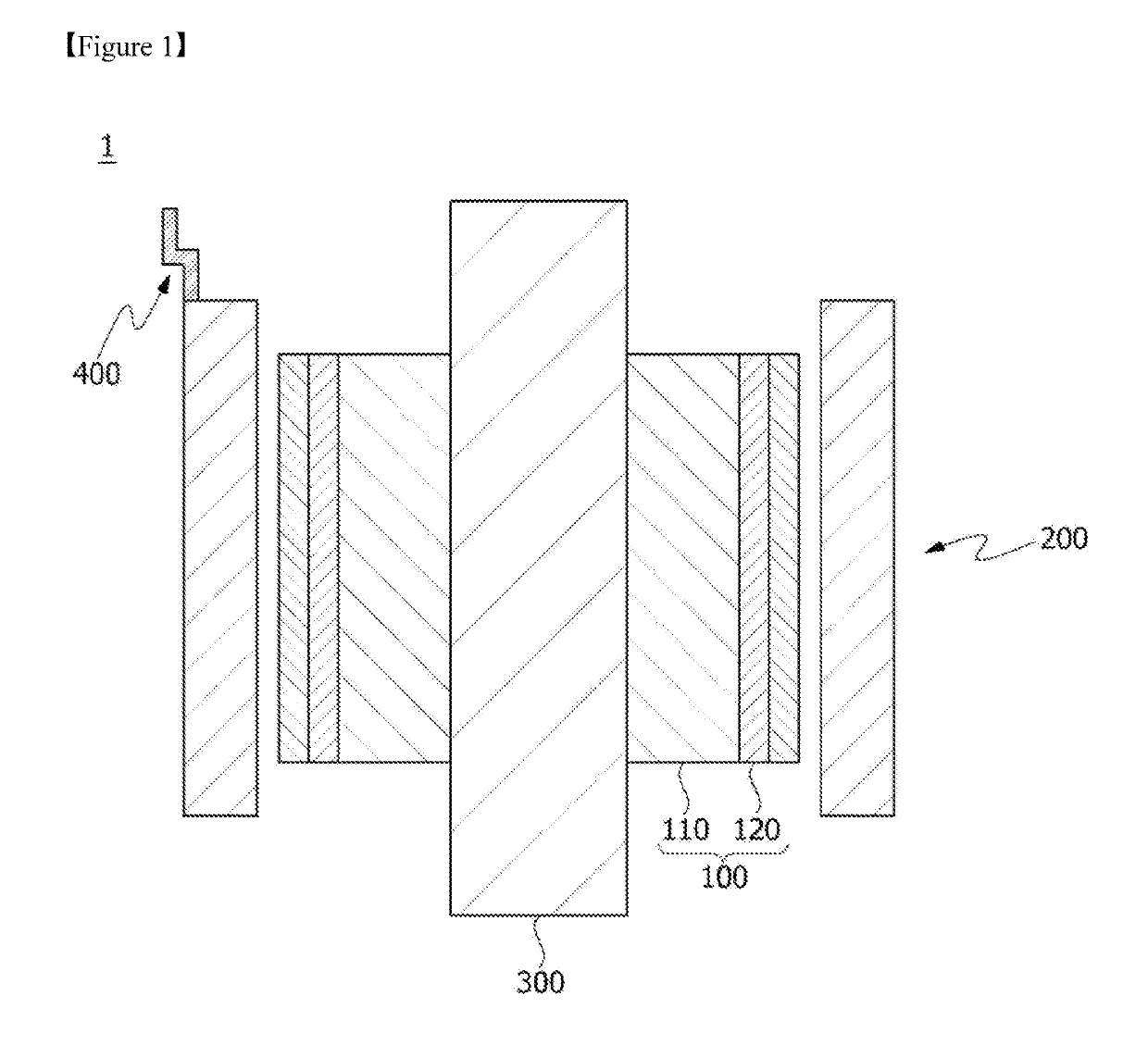
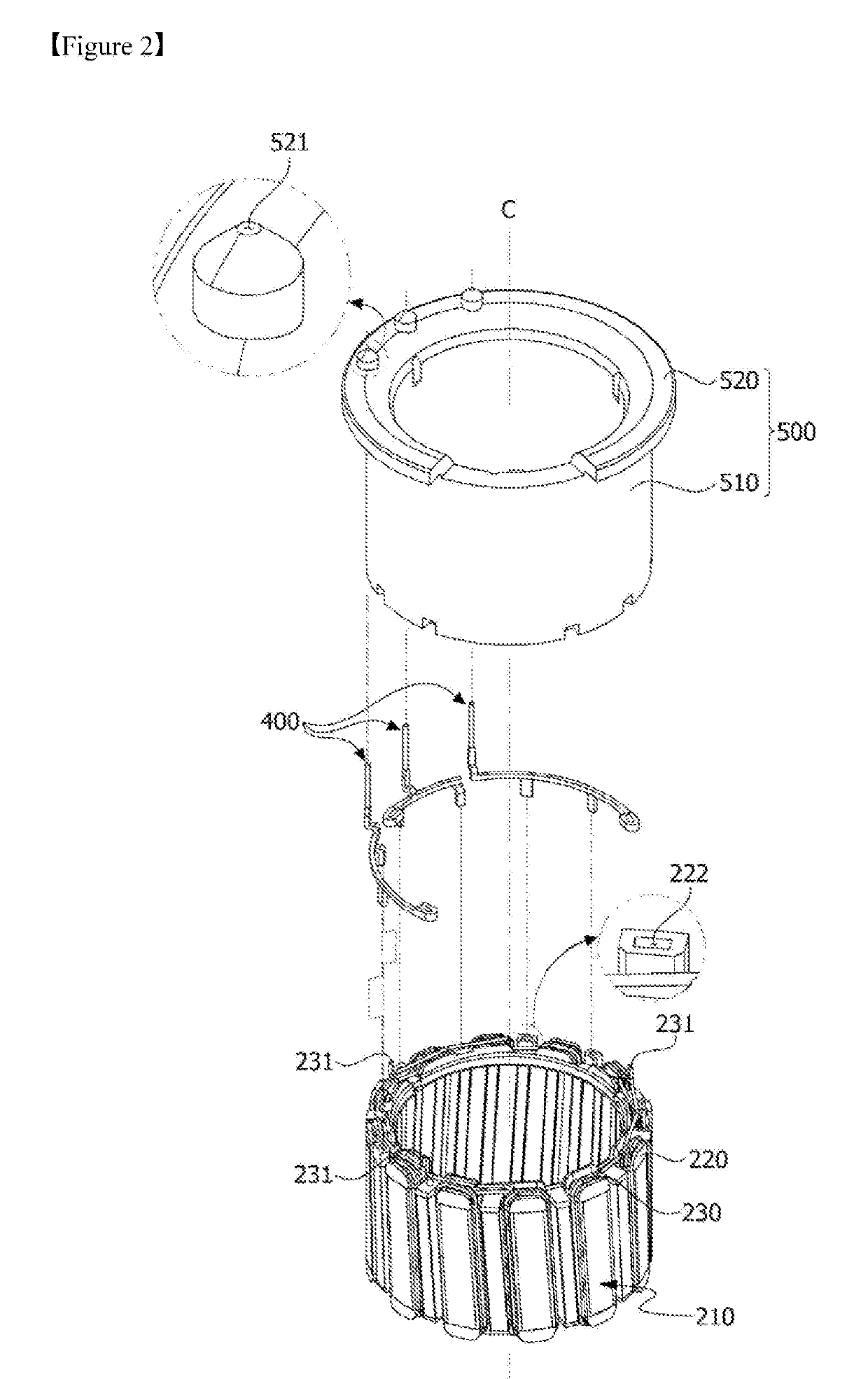
The power terminal described in this patent has a unique design that allows for simplified manufacturing and improved efficiency. The terminal includes a body, a pin portion, and two protrusions that help prevent vibration and noise while also ensuring structural stability. The three-dimensional support structure helps achieve these goals while also reducing the likelihood of motor rotation. Overall, this power terminal design is efficient, stable, and effective in preventing issues that could otherwise arise during use.

Problems solved by technology

However, since a hook-shaped coupling portion has to be formed on the power terminal and the pin has to be fused with the coupling portion to couple the pin to the power terminal, a process thereof is complicated.
Further, since the number of components such as the pin and the like increases, assembly processes are concentrated and thus costs increase.
For example, since a plurality of processes including assembling the power terminal to the stator, assembling the pin to the power terminal and then pressing the pin, fusing the pin, and fusing a wire, the number of processes increases and thus production costs increase and productivity is degraded.
Further, since the power terminal and the pin are separated structures, true position geometric tolerance required when the power terminal and the pin are coupled is difficult to satisfy.

Method used


Image

  • Power terminal and motor including same
  • Power terminal and motor including same
  • Power terminal and motor including same

Examples


Embodiment Construction

[0042]Since the present invention may be variously changed and have various embodiments, particular embodiments will be exemplified in the drawings and described. However, the present invention is not limited to the particular embodiment, and includes all changes, equivalents, and substitutes falling within the spirit and the scope of the present invention.

[0043]Further, it should be understood that, although the terms “first,”“second,” and the like may be used herein to describe various elements, the elements are not limited by the terms. The terms are only used to distinguish one element from another. For example, a first element could be termed a second element, and similarly, a second element could be termed a first element without departing from the scope of the present invention. The term “and / or” includes combinations of one or all of a plurality of associated listed items.

[0044]When predetermined components are mentioned to be “linked,”“coupled,” or “connected” to other comp...


PUM


Abstract

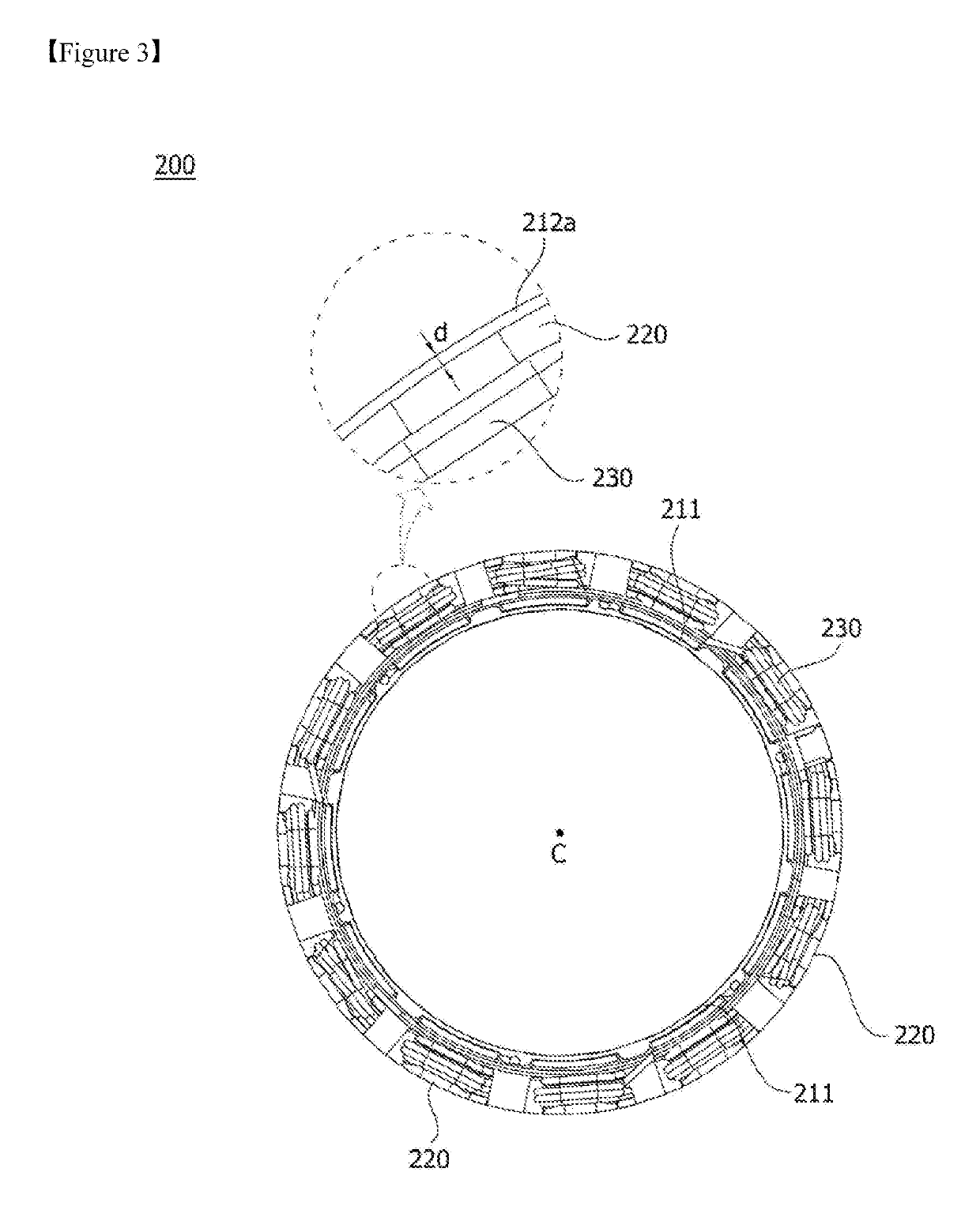
An embodiment relates to a power terminal and a motor including the same, the power terminal comprising: a body; a pin portion extending upward from the body; a coupling portion formed at one end of the body and coupled to an end of a coil; a first protrusion protruding downward from the body; and a second protrusion protruding downward from the body, wherein the second protrusion is arranged to be spaced inward or outward form the body. As a result, the power terminal can improve the productivity through process simplification while satisfying a true position geometric tolerance.

Description

TECHNICAL FIELD[0001]Embodiments relate to a power terminal and a motor including the same.BACKGROUND ART[0002]A motor generates rotating power through interaction with an electromagnetic force generated by a rotor including a plurality of magnets and a coil wound around a stator.[0003]Accordingly, the motor can include a shaft which is rotatably formed, a rotor coupled to the shaft, and a stator fixed to the inside of a housing. Here, the stator is installed with a gap along a circumference of the rotor. Further, a coil forming a rotating magnetic field is wound around the stator.[0004]Correspondingly, the coil causes electric interaction with the rotor to induce rotation of the rotor. Accordingly, when the rotor rotates, the shaft rotates.[0005]Further, the stator used in the motor may include a stator core, an insulator, and the coil. Here, the stator core may include a cylindrical-shaped main body made of a metal material, and a plurality of teeth may be formed to protrude from ...

Claims


Application Information

Patent Timeline
IPC IPC(8): H02K1/24H02K3/34H02K5/22H02K3/52
CPCH02K1/24H02K3/34H02K5/22H02K3/522H02K2201/06H02K1/165H02K2203/09H02K3/50
Inventor HONG, HOON KI
Owner LG INNOTEK CO LTD
Learn More