Composite structure having an integrated support

a composite structure and manufacturing method technology, applied in the direction of mechanical equipment, other domestic objects, rod connections, etc., can solve the problems of long and complex development process, high cost and significant lead time in the overall aircraft development and production process, and the overall manufacturing of each system, including system devices and routing, is difficult, and achieves the effect of reducing labor hours, reducing lead time, and high production efficiency

Active Publication Date: 2019-05-16
AIRBUS OPERATIONS SL
View PDF5 Cites 0 Cited by
  • Summary
  • Abstract
  • Description
  • Claims
  • Application Information

AI Technical Summary

Benefits of technology

The present invention provides a composite structure with an integrated insert for attaching hydraulic and electric systems. This simplifies the installation and maintenance tasks of the aircraft, resulting in significant savings. The methods also reduce the time needed for repair operations, minimizing the time needed to disassemble and assemble the structure.

Problems solved by technology

The overall manufacturing of each system, including system devices and routing, of the aircraft, together with its respective installation in the aircraft is difficult.
Because of these difficulties, these systems typically require a long and complex development process which involves high costs and significant lead time in the overall aircraft development and production.
These scheduled maintenance tasks, together with any additional ones coming from any function issue detected along them, have a relevant cost for the airliner and may have an impact on the aircraft departure.
The time and costs needed to install thousands of fittings are considerable and expensive.

Method used


Image

  • Composite structure having an integrated support
  • Composite structure having an integrated support
  • Composite structure having an integrated support

Examples


Embodiment Construction

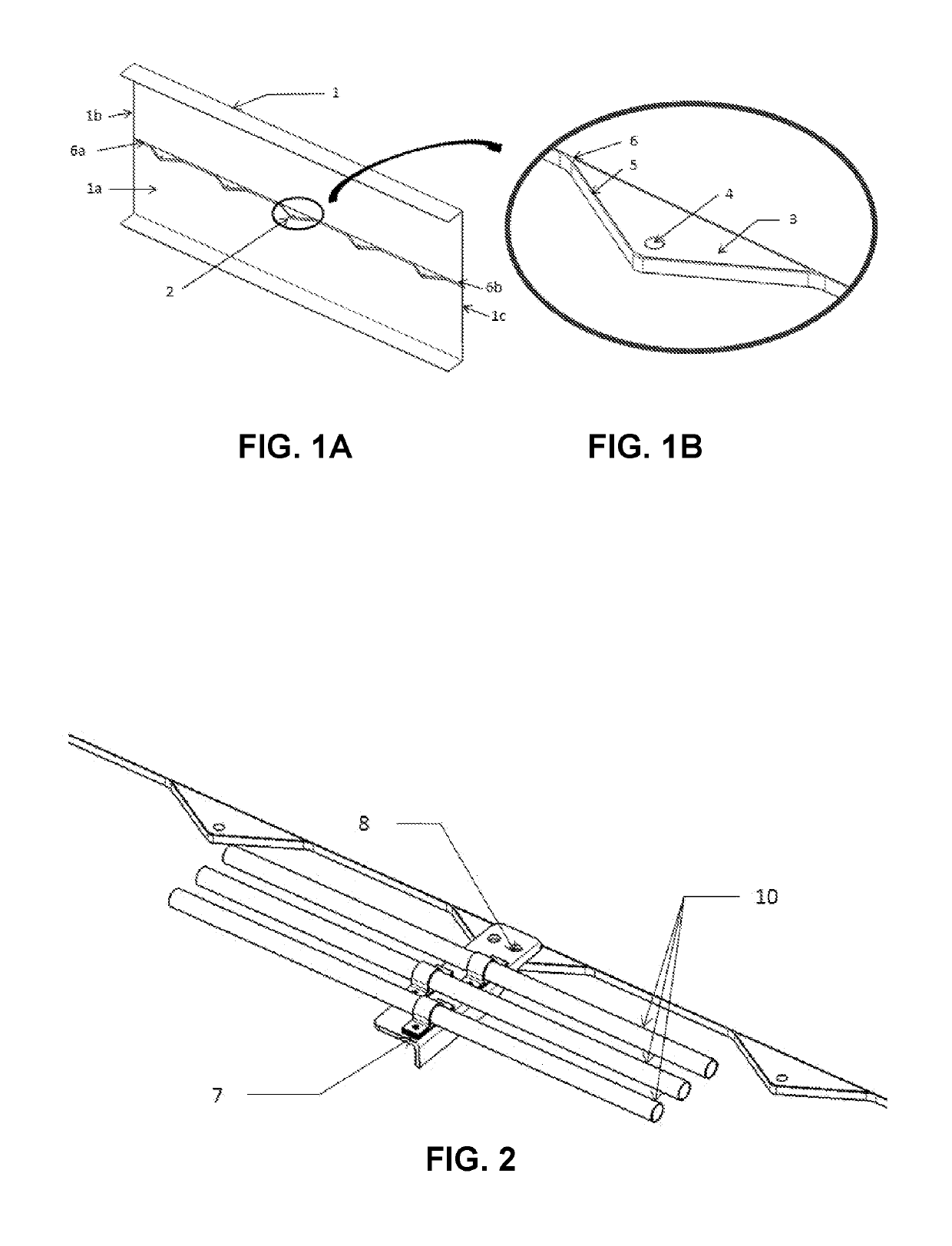
[0042]FIG. 1 shows a composite structure 1 for an aircraft according to a preferred embodiment. The composite structure 1 has at least one insert 2 for receiving attachment devices, wherein the at least one insert 2 comprises a core 3 and a composite strip arrangement.

[0043]As shown in the detailed view of FIG. 1, the composite structure 1 comprises several inserts 2 in where each core 3 contains at least one through-hole 4 intended to receive attachment devices for attaching external routing 10 to the structure 1.

[0044]Each core 3 has a major dimension for being positioned substantially transversal with respect to a first surface 1a of the composite structure 1. The core 3 may be a composite plate having a thickness substantially smaller than the length and width of the core. If the core is triangular in shape, the major dimension is the length of the base of the triangle. The major dimension of the core 3 may be the length of the longest edge of the core. Positioning the major dim...


PUM

PropertyMeasurementUnit
dimensionaaaaaaaaaa
distanceaaaaaaaaaa
timeaaaaaaaaaa

Abstract

A composite structure (1) for an aircraft, having at least one insert (2) for receiving attachment devices, each insert (2) includes a core (3) having a major dimension and containing at least one through-hole (4), and a composite strip arrangement formed by a first section (5) surrounding the core (3) and attached to said core (3) by an adhesive polymeric layer, and a second section (6) including at least one free end (6a). The first (5) and the second portion (6) of the composite strip arrangement are disposed over a first surface (1a) of the composite structure (1), such that the major dimension of the core (3) is positioned transversal to said first surface (1 a). The at least one insert (2) is co-cured with the composite structure (1).

Description

RELATED APPLICATION[0001]This application claims priority to European Patent Application 17382773-4, filed 15 Nov. 2017, the entirety of which is incorporated by reference.FIELD[0002]The present invention relates to a configuration and a manufacturing method of a composite structure for an aircraft having an integrated insert for receiving attachment devices. The invention further refers to an attachable system that includes the composite structure with the integrated insert, and an attachment device to attach external routings (ducts of the hydraulic system and wirings of the electric system) to the insert.BACKGROUND[0003]In addition to structures which support aerodynamic loads (statically and cycling), aircraft require complex systems, which are defined in the design stage and in the operating process, to ensure continued airworthiness of aircraft. Some of these systems are essential for keeping the aircraft flying, such as flight controls. These essential systems are required by...

Claims


Application Information

Patent Timeline
Patent Type & Authority Applications(United States)
IPC IPC(8): F16L3/123H02G3/00
CPCF16L3/123H02G3/26B29L2031/737B29L2031/3076B29C70/74B29C65/5014B29C65/5042B29C65/561B29C65/562B29C66/112B29C66/114B29C66/474B29C66/532B29C66/721B29C66/72143B29C66/727B29C66/73751B29C66/7392F16B2/10F16B5/0685F16B7/0433F16B9/02
Inventor HONORATO RUIZ, FRANCISCO JAVIERSANCHEZ FRANCO, DIEGORODRIGUEZ URBINA, LUISGUINALDO FERNANDEZ, ENRIQUEGARCIA NIETO, CARLOS
Owner AIRBUS OPERATIONS SL
Why Eureka
Try Eureka