Method of determining joint stress from sensor data

a sensor data and joint stress technology, applied in the field of motion analysis and biomechanics, can solve the problems of severe stress on human joints, fatigue or injury, and particularly acute stress and risks

Active Publication Date: 2019-05-16
NEWLIGHT CAPITAL LLC
View PDF1 Cites 7 Cited by
  • Summary
  • Abstract
  • Description
  • Claims
  • Application Information

AI Technical Summary

Problems solved by technology

Human joints are subject to severe stresses that may lead to fatigue or injury.
These stresses and risks are particularly acute in certain sports activities, such as baseball pitching.
These injuries result in significant time lost due to the injury itself, surgery if necessary, and the required rehab.
In Major League Baseball (MLB), the dollars lost due to contracts on the disabled list (DL) and their replacement costs continue to climb year after year, jumping in 2012 due to a correlative spike in TJ related injuries.
For a pitcher with a $10 million-dollar annual contract, that is a significant sunk cost.
While there has been a lot of research performed on overhead throwing athletes over the past 30 years, there has not been much at all in terms of definitive injury mechanisms from these research studies.
When a joint degree of freedom is isometrically held at end range of motion for some duration of time, active muscle forces are required to counteract these passive joint moments that are trying to move the joint out of the end range of motion, thereby prematurely fatiguing the same musculature that is meant to protect the joint ligaments from excessive loading during high-speed dynamic movements.
Premature fatigue of the musculature of the proximal and / or distal segments may result in altered coordination and control patterns and can subject the joint ligaments to a higher percentage of total joint loading on each action (such as each throw), thereby increasing the injury risk for the athlete.
In reality, it is very difficult to accurately measure arthrokinematics, especially during high-speed athletic movements.
As a result, methods known in the art to analyze joint stresses have generally not taken into account arthrokinematic effects.

Method used


Image

  • Method of determining joint stress from sensor data
  • Method of determining joint stress from sensor data
  • Method of determining joint stress from sensor data

Examples


Embodiment Construction

[0024]A method of determining joint stress from sensor data will now be described. In the following exemplary description, numerous specific details are set forth in order to provide a more thorough understanding of embodiments of the invention. It will be apparent, however, to an artisan of ordinary skill that the present invention may be practiced without incorporating all aspects of the specific details described herein. In other instances, specific features, quantities, or measurements well known to those of ordinary skill in the art have not been described in detail so as not to obscure the invention. Readers should note that although examples of the invention are set forth herein, the claims, and the full scope of any equivalents, are what define the metes and bounds of the invention.

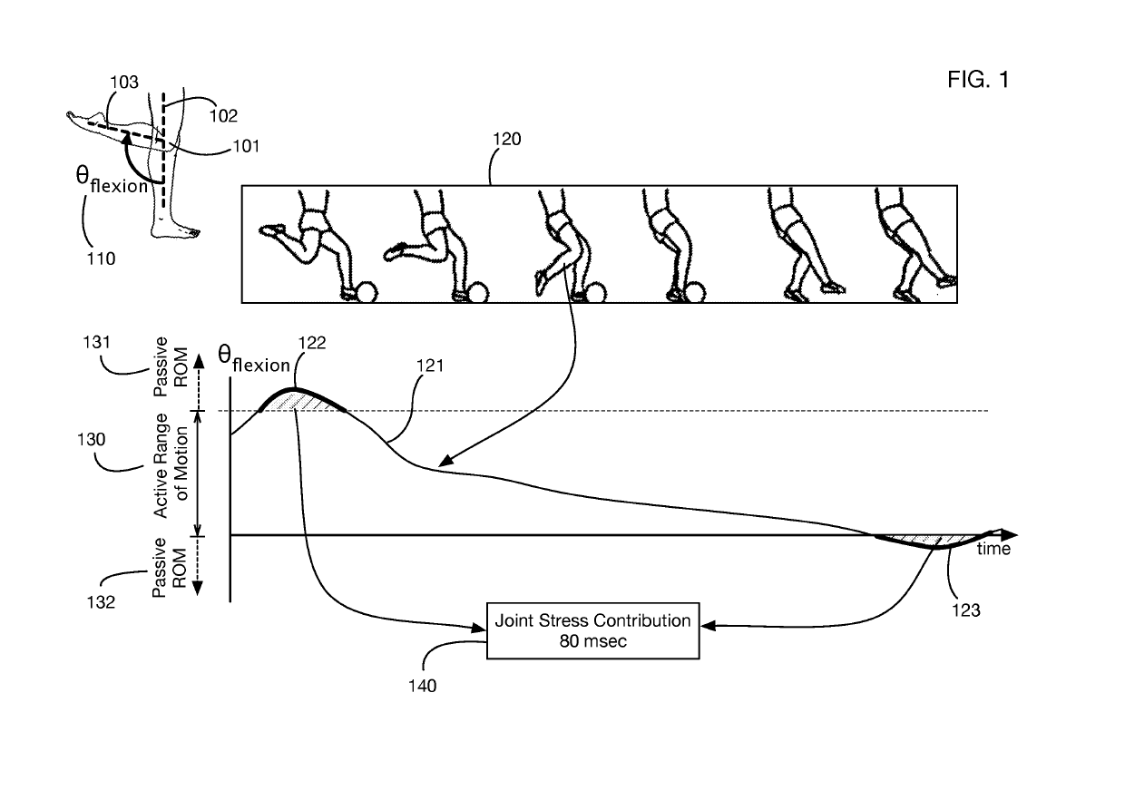
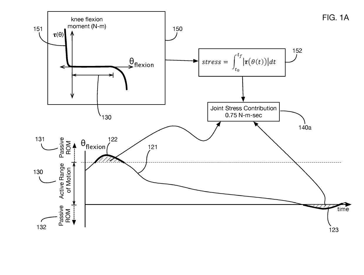
[0025]FIG. 1 shows an illustrative application of one or more embodiments of the invention. The method of the invention may be applied to analyzing any type or types of stress on any joint or join...


PUM


Abstract

A method of calculating the stress on a joint by determining when a joint angle is outside the normal range of motion for the joint. Applications include analysis of elbow joint stress for baseball pitchers, for example to mitigate the risk of injury to the ulnar collateral ligament (UCL). During a movement such as a baseball pitch, sensor data is collected to track the position, orientation, or motion of body segments; joint angles are derived from this sensor data. Joint angles are then compared to a range of motion, which may be measured for each individual. Joint stress contributions from movements that exceed the range of motion may be combined over time to calculate cumulative joint fatigue. This joint fatigue measure may for example be used for pitchers to quantify recovery periods (days off) and future workloads (such as maximum pitch counts).

Description

[0001]This application is a continuation of U.S. Utility patent application Ser. No. 15 / 815,571 filed 16 Nov. 2017, issued as U.S. Pat. No. 10,121,066, the specification of which is hereby incorporated herein by reference.BACKGROUND OF THE INVENTIONField of the Invention[0002]One or more embodiments of the invention are related to the fields of motion analysis and biomechanics. More particularly, but not by way of limitation, one or more embodiments of the invention enable a method that determines the stress on a joint, such as an elbow for example, using sensor data.Description of the Related Art[0003]Human joints are subject to severe stresses that may lead to fatigue or injury. These stresses and risks are particularly acute in certain sports activities, such as baseball pitching. In baseball, for example, injury to the ulnar collateral ligament (UCL) commonly occurs in pitchers, with an increasing incidence in recent years. The UCL is located on the inside of the (medial) elbow ...

Claims


Application Information

Patent Timeline
Patent Type & Authority Applications(United States)
IPC IPC(8): G06K9/00A61B5/11A61B5/00A63B69/00A63B24/00
CPCA61B5/1128A63B2069/0006A63B69/0002G06K9/00342A61B5/4528A61B5/112A63B2024/0009A61B5/458A61B5/4585A61B2503/10A61B2562/0219A61B2562/04G06V40/23G06V40/28A61B5/1122A61B5/1116A61B5/7242
Inventor CHERVENY, PATRICKTHORNBRUE, JAMES R.BOSE, BHASKAR
Owner NEWLIGHT CAPITAL LLC
Why Eureka
Try Eureka