Spin current assisted magnetoresistance effect device

a technology of assisted magnetoresistance and effect device, which is applied in the direction of magnetic bodies, instruments, substrate/intermediate layer, etc., can solve the problems of inability to perform appropriate writing and limit the current that can flow through thin wiring, and achieve the effect of high writing speed

Active Publication Date: 2019-05-16
TDK CORPARATION
View PDF0 Cites 19 Cited by
  • Summary
  • Abstract
  • Description
  • Claims
  • Application Information

AI Technical Summary

Benefits of technology

[0024]According to the present invention, a spin current assisted magnetoresistance effect device that can assist magnetization reversal of a magnetoresistance effect element part using a pure spin current and has a high writing speed can be realized.

Problems solved by technology

In the system using a magnetic field, there are cases in which, when the size of the element is decreased, there is a limit on a current that can flow through a thin wiring, and appropriate writing may not be able to be performed.

Method used


Image

  • Spin current assisted magnetoresistance effect device
  • Spin current assisted magnetoresistance effect device
  • Spin current assisted magnetoresistance effect device

Examples


Embodiment Construction

[0038]Hereinafter, embodiments will be described in detail with reference to the drawings. In the drawings used in the following description, in order to allow easy understanding of aspects of the embodiments, characteristic portions may be represented in enlarged scales for the convenience of the description, and the dimensions, the proportions, and the like of each constituent element may be different from actual values thereof. Materials, dimensions, and the like represented in the following description are examples, and thus, the embodiments are not limited thereto, and may be appropriately changed in a range in which the effects of the embodiments are accomplished.

(Spin Current Assisted Magnetoresistance Effect Device)

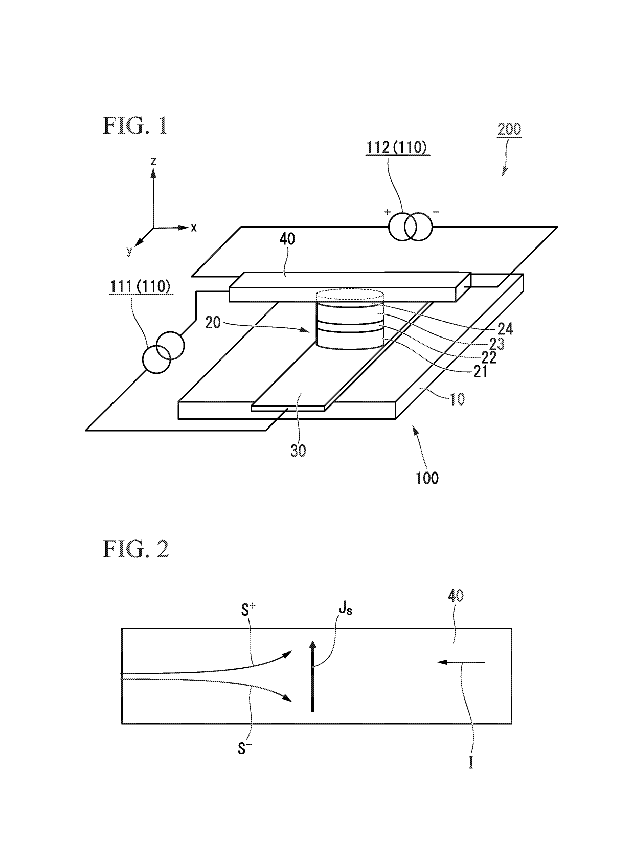
[0039]FIG. 1 is a perspective view schematically illustrating a spin current assisted magnetoresistance effect device according to this embodiment. The spin current assisted magnetoresistance effect device 200 illustrated in FIG. 1 includes a spin current assisted...


PUM

PropertyMeasurementUnit
thicknessaaaaaaaaaa
atomic numberaaaaaaaaaa
timeaaaaaaaaaa

Abstract

A spin current assisted magnetoresistance effect device includes: a spin current assisted magnetoresistance effect element including a magnetoresistance effect element part and a spin-orbit torque wiring; and a controller electrically connected to the spin current assisted magnetoresistance effect element. In a portion in which the magnetoresistance effect element part and the spin-orbit torque wiring are bonded, an STT inversion current flowing through the magnetoresistance effect element part and an SOT inversion current flowing through the spin-orbit torque wiring merge or are divided, and the controller is configured to be capable of performing control for applying the STT inversion current to the spin current assisted magnetoresistance effect element at the same time as an application of the SOT inversion current or a time application of the SOT inversion current.

Description

TECHNICAL FIELD[0001]The present invention relates to a spin current assisted magnetoresistance effect device that can be applied to a high-frequency electronic component such as a magnetic head or a high-frequency filter, a magnetic memory, and the like. Priority is claimed on Japanese Patent Application No. 2016-110414, filed on Jun. 1, 2016, the content of which is incorporated herein by reference.BACKGROUND ART[0002]As magnetoresistance effect elements, a giant magnetoresistance (GMR) element formed by a multi-layered film with a ferromagnetic layer and a nonmagnetic layer and a tunnel magnetoresistance (TMR) element using an insulating layer (a tunnel barrier layer or a barrier layer) as a nonmagnetic layer are known. Generally, a TMR element has higher element resistance than a GMR element and has a magnetoresistance (MR) ratio higher than a GMR element. A TMR element has attracted attention as an element for a magnetic sensor, a high-frequency component, a magnetic head, and ...

Claims


Application Information

Patent Timeline
Patent Type & Authority Applications(United States)
IPC IPC(8): G11C11/16H01L43/02H01L27/22H01F10/32
CPCG11C11/161H01L43/02H01L27/222H01F10/3254H01F10/329G11C11/1675H01F10/3286H01F10/324H10N50/80H10N50/10G11C11/16H01L27/105H10B99/00H10B61/00H10N52/00
Inventor SASAKI, TOMOYUKIOIKAWA, TOHRU
Owner TDK CORPARATION
Why Eureka
Try Eureka