Compact delivery pulmonary treatment systems and methods for improving pulmonary function

a pulmonary treatment system and pulmonary function technology, applied in the field of pulmonary diseases, can solve the problems of complex positioning of patient can present several difficulties to practitioners, and complicating the complex of positioning pulmonary treatment systems in airways

Pending Publication Date: 2019-05-23
HOLAIRA INC
View PDF0 Cites 6 Cited by
  • Summary
  • Abstract
  • Description
  • Claims
  • Application Information

AI Technical Summary

Benefits of technology

[0013]Pulmonary treatment systems can also be delivered using a rigid bronchoscope. Rigid bronchoscopes typically consist of a large, inflexible tube that encloses a telescope, light source, and working channels. The working channels are generally large enough to allow passage of a variety of instruments related to the treatment of the lungs. A practitioner can first insert the rigid bronchoscope, and then pass the treatment instrument through the working channel. In this way, the rigid bronchoscope shields the passage of treatment instrument past sensitive areas, such as the vocal chords. However, due to their large size and inflexibility, rigid bronchoscopes are limited in their ability to reach smaller and more distal airways. Rigid bronchoscopy is also more invasive than flexible bronchoscopy, and is typically performed in the operating room under general anesthesia.
[0086]The second side of the airway can include a thin walled septum of the airway at the first location. The airway can be a right main bronchus. The first treatment location can be in the right main bronchus proximal of an upper lobe bronchus and the first side is the lateral wall of the right main bronchus. The second treatment location can be the right main bronchus distal of the carina and the second side wall is the medial wall of the right main bronchus. The delivering energy at the first and second location can create lesions in the first and second locations that overlap when viewed along the airway so that, when taken together, the lesions form a pair of offset lesions that disrupt nerve activity around an entire circumference of the airway wall.

Problems solved by technology

It has been recognized that delivering a pulmonary treatment system to a treatment site in an airway of a patient can present several difficulties to practitioners.
The complexity of positioning a pulmonary treatment system in an airway can be further compounded when a bronchoscope is used in conjunction with the pulmonary treatment system.

Method used


Image

  • Compact delivery pulmonary treatment systems and methods for improving pulmonary function
  • Compact delivery pulmonary treatment systems and methods for improving pulmonary function
  • Compact delivery pulmonary treatment systems and methods for improving pulmonary function

Examples


Embodiment Construction

I. Overview

[0186]FIGS. 1-6 provide an overview of human lung function and the role the nervous system can play in a diseased lung. FIGS. 7-15 provide an overview of an example treatment applied to the pulmonary system according to one aspect of the present disclosure. FIGS. 16 and 17 provide an overview of the effects of the treatment illustrated in FIGS. 7-15.

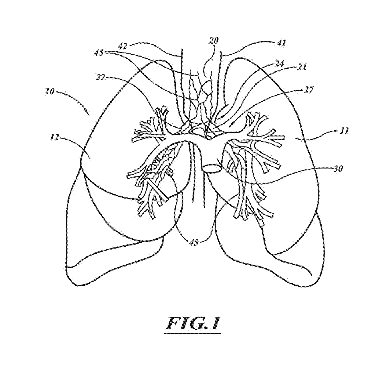
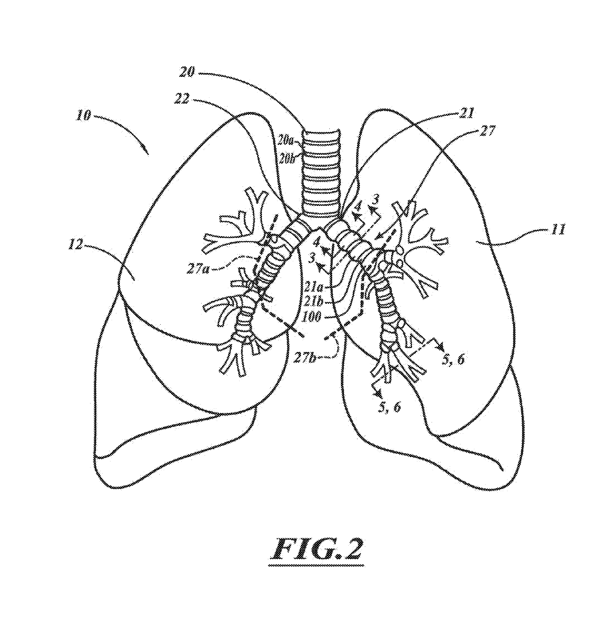
[0187]FIG. 1 illustrates human lungs 10 having a left lung 11 and a right lung 12. A trachea 20 extends downwardly from the nose and mouth and divides into a left main bronchus 21 and a right main bronchus 22. The left main bronchus 21 and right main bronchus 22 each branch to form lobar, segmental bronchi, and sub-segmental bronchi, which have successively smaller diameters and shorter lengths in the outward direction (i.e., the distal direction). A main pulmonary artery 30 originates at a right ventricle of the heart and passes in front of a lung root 24. At the lung root 24, the artery 30 branches into a left and a right pu...


PUM


Abstract

A pulmonary treatment system includes a compact configuration for delivery to a first airway of a patient. An energy delivery system of the pulmonary treatment system delivers energy to target tissue in or along an airway wall of the first airway to reduce airway resistance in a second airway distal to the first airway. The pulmonary treatment system protects tissue in the airway wall of the first airway located between the target tissue and the energy delivery system by at least one of thermodynamically cooling, circulating a liquid coolant through the pulmonary treatment system, and shielding a portion of the energy delivery system.

Description

RELATED APPLICATIONS[0001]This application is a continuation of application Ser. No. 13 / 894,920 filed May 15, 2013, which claims the benefit of U.S. Provisional Application No. 61 / 786,203 filed Mar. 14, 2013 and U.S. Provisional Application No. 61 / 649,154 filed May 18, 2012, each of which is hereby fully incorporated herein by reference.BACKGROUNDTechnical Field[0002]The present invention generally relates to the field of treatment of the pulmonary diseases.Description of the Related Art[0003]Pulmonary diseases may cause a wide range of problems that adversely affect performance of the lungs. Pulmonary diseases, such as asthma and chronic obstructive pulmonary disease (“COPD”), may lead to increased airflow resistance in the lungs. Mortality, health-related costs, and the size of the population having adverse effects due to pulmonary diseases are all substantial. These diseases often adversely affect quality of life. Symptoms are varied but often include cough; breathlessness; and w...

Claims


Application Information

Patent Timeline
Patent Type & Authority Applications(United States)
IPC IPC(8): A61B18/18A61N7/02A61B18/14
CPCA61B18/1815A61N7/022A61B18/1492A61B2018/00095A61B2018/00083A61B2018/00017A61B2018/00267A61B2018/00541A61B2018/0022
Inventor MAYSE, MARTIN L.DIMMER, STEVENDEEM, MARKSTREETER, JOHNKAVECKIS, RYANHARSHMAN, EDWARD S.
Owner HOLAIRA INC
Why Eureka
Try Eureka