Surveying Instrument And Surveying Instrument System

a technology of surveying instruments and instruments, which is applied in the direction of instruments, measurement devices, and using reradiation, can solve the problems of large inertia of the telescope itself, difficult horizontal rotation/vertical rotation of the telescope, and large inertia of the support mechanism unit, etc., to achieve rapid response to changes, high response, and high speed rotation

Active Publication Date: 2019-05-23
KK TOPCON
View PDF3 Cites 12 Cited by
  • Summary
  • Abstract
  • Description
  • Claims
  • Application Information

AI Technical Summary

Benefits of technology

[0015]According to the present invention, a distance measuring light projecting module for projecting a distance measuring light, a light receiving module for receiving a reflected distance measuring light which is the distance measuring light retro-reflected by an object to be measured and a background light incident coaxially with the reflected distance measuring light, a distance measuring unit for receiving the reflected distance measuring light and performing a distance measurement, an image pickup module for receiving the background light separated from the reflected distance measuring light and acquiring a background image, an optical axis deflector for integrally deflecting an optical axis of the distance measuring light and an optical axis of the background light, and an arithmetic control module for controlling the optical axis deflector are provided, and the optical axis deflector has a pair of disk prisms in which two or more prism columns are arrayed in parallel, a rotary driving module for rotating the disk prisms individually, and a projecting direction detecting module for detecting a rotation angle of each of the disk prisms. As a result, the disk prism which changes the distance measuring optical axis has a light weight, is capable of high-speed rotation and high response, and is capable of rapid response to a change in a sight direction.
[0016]Further, according to the present invention, a distance measuring light, a light receiving module for receiving a reflected distance measuring light, which is the distance measuring light retro-reflected by an object to be measured, and a reflected tracking light incident coaxially with the reflected distance measuring light, a distance measuring unit for receiving the reflected distance measuring light and performing a distance measurement, a tracking module for projecting a tracking light with the same optical axis as a distance measuring optical axis, for receiving the reflected tracking light separated from the reflected distance measuring light, for detecting a deviation between the reflected tracking light and the distance measuring optical axis, for calculating the tracking control information based on the deviation and for performing the tracking, an optical axis deflector for integrally deflecting the distance measuring light and the tracking light, and an arithmetic control module for controlling the optical axis deflector and for directing the distance measuring optical axis toward the object to be measured and performing a measurement are provided, and the optical axis deflector has a pair of disk prisms in which two or more prism columns is arrayed in parallel, a rotary driving module for rotating the disk prisms individually, and a projecting direction detecting module for detecting a rotation angle of each of the disk prisms, wherein the tracking control information includes a detection result of the projecting direction detecting module, and the optical axis deflector is configured to be controlled based on the tracking control information. As a result, the disk prism which deflects the distance measuring optical axis has a light weight, is capable of high-speed rotation and high response, and is capable of high-speed and high-responsive tracking.
[0017]Furthermore, according to the present invention, a supporting unit for installing the surveying instrument, and an installment base unit which is a support portion of the surveying instrument are provided, and the installment base unit has a rotary driving module which rotates / drives the surveying instrument in a horizontal direction and in a vertical direction, and an angle detector which detects a horizontal rotation angle and a vertical rotation angle, and the arithmetic control module is configured to controls a rotary driving module of the optical axis deflector and to perform a tracking of an object to be measured and is configured to control the rotary driving module of the installment base unit and the rotary driving module of the optical axis deflector such that a deflection angle of the distance measuring optical axis becomes 0. As a result, the disk prism which deflects the distance measuring optical axis has a light weight, is capable of high-speed rotation and high response, is capable of high-speed and high-responsive tracking, and is capable of the tracking at high-speed and at high-response.

Problems solved by technology

However, the magnification of the telescope is high, a field angle is as extremely small as approximately 2°, and further, the telescope itself has a large inertia.
Further, since a support mechanism of the telescope requires high rigidity, a support mechanism unit also has a large inertia.
Thus, at a change of the object to be measured, it is difficult to horizontally rotate / vertically rotate the telescope at a high speed and to rapidly sight the object to be measured, and further, if movement of the object to be measured is fast during tracking, the movement cannot be followed but the object to be measured goes out of a visual field of the telescope in some cases.
Once the object to be measured goes out of the visual field, since the field angle of the telescope is narrow, it takes time to catch the object to be measured again, which causes deterioration in workability of the measurement.

Method used


Image

  • Surveying Instrument And Surveying Instrument System
  • Surveying Instrument And Surveying Instrument System
  • Surveying Instrument And Surveying Instrument System

Examples


Embodiment Construction

[0025]A description will be given below on an embodiment of the present invention by referring to the attached drawings.

[0026]A surveying instrument system according to the embodiment of the present invention will be described by FIG. 1, FIG. 2, and FIG. 3.

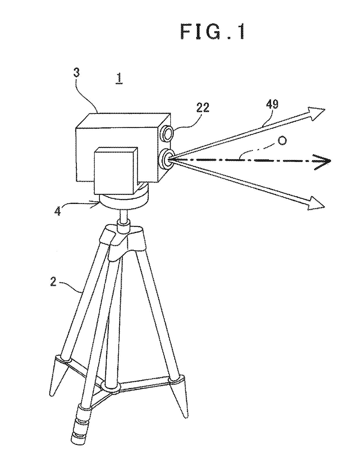
[0027]In FIG. 1, reference numeral 1 denotes a surveying instrument system, reference character O denotes a distance measuring optical axis in a state where an optical axis is not deflected, and the distance measuring optical axis at this time is made a reference optical axis.

[0028]The surveying instrument system 1 mainly has a tripod 2 as a supporting unit, a surveying instrument 3 and an installment base unit 4 which is a support portion of the surveying instrument 3.

[0029]The installment base unit 4 is mounted on an upper end of the tripod 2, and the surveying instrument 3 is supported by the installment base unit 4 rotatably in an up-and-down direction and in a left-and-right direction, respectively.

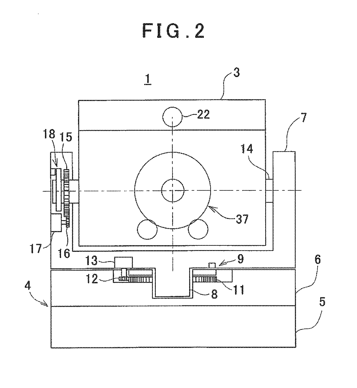
[0030]As illustrated in FIG...


PUM


Abstract

A distance measuring light projecting module comprises a light receiving module for receiving a reflected distance measuring light and a background light, a distance measuring unit for receiving the reflected distance measuring light and performs a distance measurement, an image pickup module for receiving the background light and for acquiring a background image, an optical axis deflector for integrally deflecting an optical axis of the distance measuring light and an optical axis of the background light, and an arithmetic control module for controlling the optical axis deflector, wherein the optical axis deflector has a rotary driving module for rotating a pair of disk prisms individually, and a projecting direction detecting module for detecting a rotation angle of each of the disk prisms.

Description

BACKGROUND OF THE INVENTION[0001]The present invention relates to a surveying instrument with a tracking function and a surveying instrument system.[0002]There is a total station as a surveying instrument with the tracking function. In the total station, an object to be measured is sighted by a telescope with high magnification also serving as a distance measuring optical system, a measurement is performed, and further, the telescope is horizontally rotated / vertically rotated, a different object to be measured is sighted or the like, and the different objects to be measured are sequentially sighted and the measurement is performed, respectively. Alternatively, in the total station, the telescope is horizontally rotated / vertically rotated while following movement of the object to be measured, the object to be measured is sighted while the object to be measured is being tracked, and the measuring is carried out.[0003]However, the magnification of the telescope is high, a field angle i...

Claims


Application Information

Patent Timeline
Patent Type & Authority Applications(United States)
IPC IPC(8): G01S7/481G01S7/48G01S17/08G01S17/89G01S17/86
CPCG01S7/4817G01S7/4808G01S17/08G01S17/89G01C15/002G01S17/42G01S17/66G01S7/4972G01S17/86
Inventor OHTOMO, FUMIOISHINABE, IKUOKUMAGAI, KAORU
Owner KK TOPCON
Why Eureka
Try Eureka