Electric charging device with fluid cooling

a charging device and internal combustion engine technology, applied in the direction of liquid fuel engines, machines/engines, mechanical equipment, etc., can solve the problems of affecting the effectiveness and efficiency of exhaust gas turbochargers, components heat up strongly, and the rotation rate or performance of components is dependent, so as to facilitate the cooling efficiency of stators and reduce material costs , the effect of small design

Active Publication Date: 2019-05-23
BORGWARNER INC
View PDF0 Cites 0 Cited by
  • Summary
  • Abstract
  • Description
  • Claims
  • Application Information

AI Technical Summary

Benefits of technology

[0018]In a third embodiment, the invention comprises a charging device for an internal combustion engine with a shaft, a compressor wheel arranged on the shaft, a stator housing, and a stator, wherein the stator is arranged within the stator housing. The stator has windings and sealing compound. In addition, the charging device comprises a rotor arranged on the shaft and a cooling channel extending axially for accommodating a coolant between the stator housing and the stator. A first seal is provided in the axial direction between the stator housing and a first end of the stator and a second seal is provided in the axial direction between the stator housing and a second end of the stator. Walls of the cooling channel are formed directly by the stator housing and the sealing compound of the stator. This may be facilitated, for example, by the use of a fluid-tight, in particular a water-tight sealing compound. Alternatively, a fluid-tight, in particular a water-tight membrane surrounds the stator. The walls of the cooling channel are then formed by the membrane and the stator housing. Advantageously in this embodiment of the charging device as well, the stator is directly flushed by cooling fluid and thus an efficient cooling of the stator is facilitated. Likewise, the stator housing may be produced in a die casting method, as no cooling channels need to be provided in the stator housing. This means that a smaller design of the stator housing may be realized, and a reduction of the material costs as well as a simpler and more cost-efficient production of the charging device.

Problems solved by technology

The disadvantage in exhaust gas turbochargers is that their rotation rate or performance is dependent on the exhaust gas flow, thus on the engine loads.
At low engine speeds, in particular, this may negatively affect the effectiveness and efficiency of exhaust gas turbochargers.
At high loads and during output peaks, these components heat up strongly.
However, these types of charging devices have a large design for the stator housing and a low efficiency for cooling the stator.

Method used


Image

  • Electric charging device with fluid cooling
  • Electric charging device with fluid cooling

Examples


second embodiment

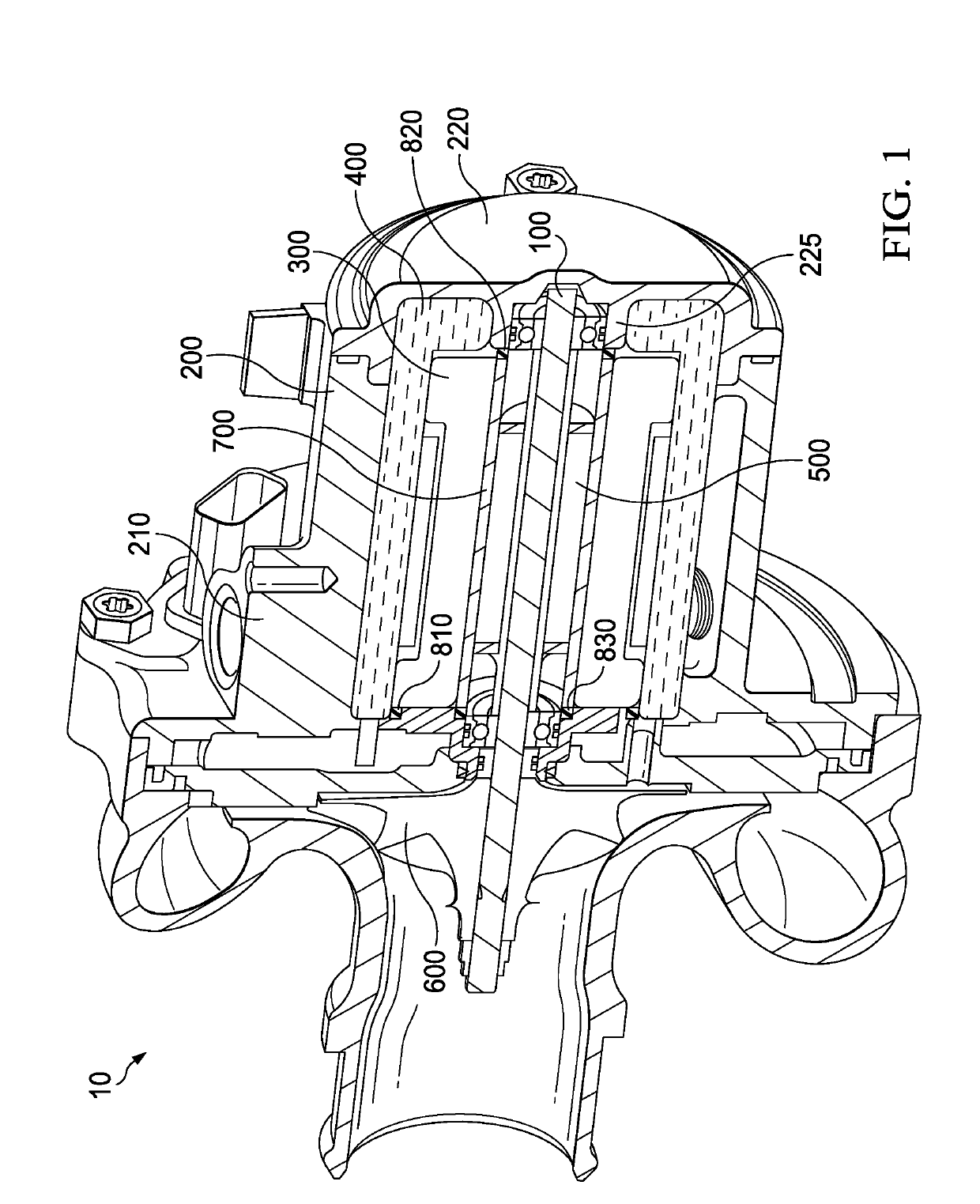
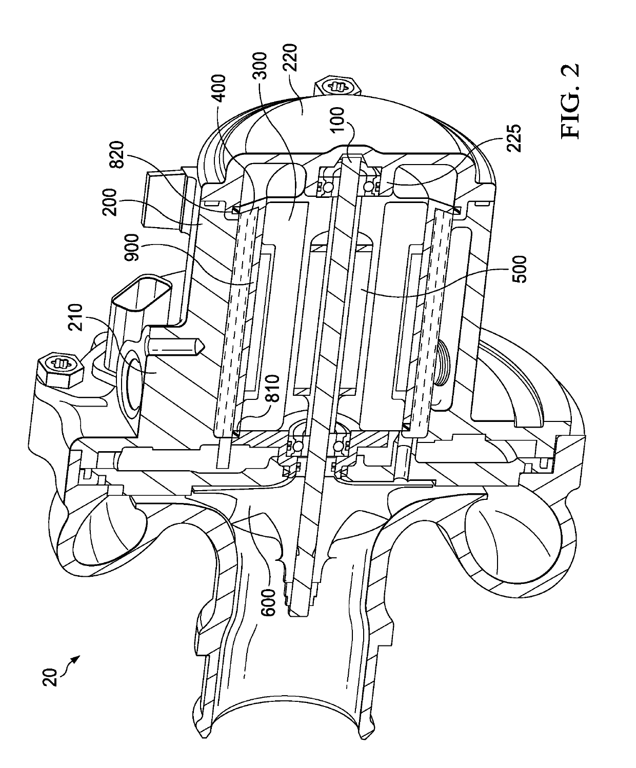
[0030]FIG. 2 shows charging device 20 according to the invention. Charging device 20 has in turn a shaft 100, a compressor wheel 600 arranged on shaft 100, a stator housing 200, and a stator 300. Charging device 20 also comprises a rotor 500 arranged on shaft 100 and a cooling channel 400 extending axially for accommodating a coolant. In contrast to the embodiment of FIG. 1, charging device 20 of FIG. 2 does not have a split tube. A separation tube 900 is arranged for this purpose between stator 300 and stator housing 200 so that cooling channel 400 is formed in the radial direction between separation tube 900 and stator housing 200. In an alternative embodiment, separation tube 900 and additionally split tube 400 shown in FIG. 1 may be provided.

[0031]In charging device 20 of FIG. 2, it is advantageous that an efficient cooling of stator 300 is likewise facilitated, as the coolant is separated from stator 300 only by thin separation tube 900. In addition, stator housing 200 may be p...

third embodiment

[0036]the charging device, which is not shown in the figures (reference numerals for correspondingly identical components will be retained in this case for better understanding), may likewise have a shaft 100, a compressor wheel 600 arranged on shaft 100, a stator housing 200, and a stator 300. The stator in turn has windings and sealing compound. In addition, the charging device comprises rotor 500 arranged on shaft 100 and an axially extending cooling channel 400 for accommodating a coolant between stator housing 200 and stator 300. A first seal 810 is provided in the axial direction between stator housing 200 and a first end (proximal with respect to compressor wheel 600) of stator 300, and a second seal is provided in the axial direction between stator housing 200 and a second end (distal with respect to compressor wheel 600) of stator 300. In contrast to the other embodiments, there is no separation tube and no split tube, and the seals are arranged on both sides directly betwe...


PUM


Abstract

A charging device for an internal combustion engine with a shaft, a compressor wheel arranged on the shaft, a stator housing and a stator. The stator is arranged within the stator housing. A rotor is arranged on the shaft and a cooling channel for accommodating a coolant extends axially between the stator housing and the stator. A split tube is provided between the rotor and stator. A first seal is provided in the axial direction between the stator housing and a first end of the stator and a second seal is provided in the axial direction between the stator housing and a first end of the split tube. Alternatively to the split tube, a separation tube is arranged between the stator and the stator housing so that the cooling channel is formed in the radial direction between the separation tube and the stator housing.

Description

FIELD OF THE INVENTION[0001]The present invention relates to an electric charging device for an internal combustion engine with FLUID cooling.BACKGROUND INFORMATION[0002]Increasingly more vehicles of the more recent generation are equipped with charging devices. In order to achieve the target demands and the legal requirements, it is imperative to promote development in the complete drive train and also to optimize the individual components as well as the system as a whole with respect to their reliability and efficiency.[0003]For example, exhaust gas turbochargers are known in which a turbine wheel is driven by the exhaust gas flow of the internal combustion engine. A compressor wheel, which is arranged with a turbine wheel on a mutual shaft, compresses the fresh air taken in for the engine. By this means, the air or oxygen amount, available to the engine for combustion, is increased, which in turn leads to an increased output of the internal combustion engine. The disadvantage in ...

Claims


Application Information

Patent Timeline
Patent Type & Authority Applications(United States)
IPC IPC(8): H02K9/197F02B39/00F02B39/10F04D17/10F04D25/06F04D29/58H02K5/20
CPCH02K9/197F02B39/005F02B39/10F04D17/10F04D25/06F04D29/5806H02K5/20H02K5/128H02K5/203
Inventor RACHOR, CHRISTOPH
Owner BORGWARNER INC
Why Eureka
Try Eureka