A method and a system for controlling the driving engine and hydraulic pumps of a hydraulic machine, as well as a pile driving rig

a technology of hydraulic machines and hydraulic pumps, which is applied in adaptive control, servomotors, instruments, etc., can solve the problems of unnecessarily high energy consumption and emissions of driving engines, inadequate use of machines with respect to fuel economy and emissions, and high energy consumption of driving engines. , to achieve the effect of reducing energy consumption, improving the energy efficiency of driving engines, and reducing energy consumption

Inactive Publication Date: 2019-05-30
JUNTTAN OY
View PDF0 Cites 4 Cited by
  • Summary
  • Abstract
  • Description
  • Claims
  • Application Information

AI Technical Summary

Benefits of technology

[0005]It is the aim of the invention to provide a method for reducing the energy consumption and improving the energy efficiency of the driving engine of a hydraulic machine, as well as for making the driving engine of the hydraulic machine always opera

Problems solved by technology

A drawback of the present method is that the output capacity of the driving engine (that is, the desired rotation speed and torque) always have to be adjusted according to the maximum output required for performing the operation at hand or the functions of the machine, although carrying out the functions of the operation includes many steps in which this maximum hydraulic output (that is, volume flow and pressure of pressurized medium) is not needed all the time.
As a result, much of the hydraulic energy produced by the system and thereby of the energy used by the driving engine is consumed in redundant circulati

Method used


Image

  • A method and a system for controlling the driving engine and hydraulic pumps of a hydraulic machine, as well as a pile driving rig
  • A method and a system for controlling the driving engine and hydraulic pumps of a hydraulic machine, as well as a pile driving rig
  • A method and a system for controlling the driving engine and hydraulic pumps of a hydraulic machine, as well as a pile driving rig

Examples


Embodiment Construction

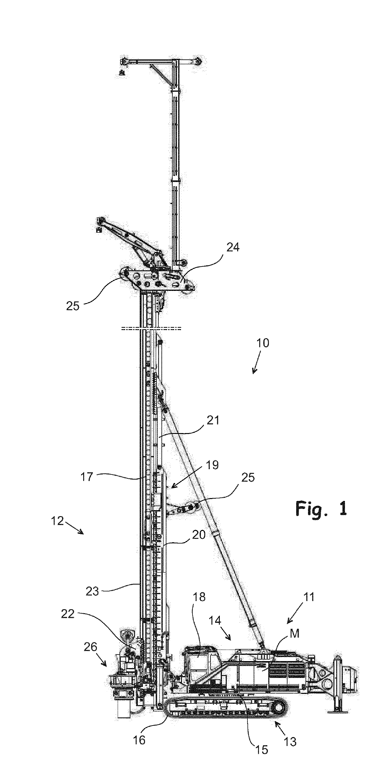
[0016]FIG. 1 shows a machine 10 which is a so-called combined pile driving rig for driving bored piles, rammed piles or grooved / steel piles into the ground by vibration or pressing. When the pile driving rig 10 is used for driving bored piles, a bore motor as shown in FIG. 1 is mounted on a slide 22 in a working device 26 on a leader 17. When rammed piles are driven into the ground, the hammer of the pile driving apparatus is mounted on the slide 22, and when grooved / steel piles are driven into the ground by vibration, a vibrator is mounted on the slide 22.

[0017]The machine 10 of FIG. 1 comprises a base machine 11 and a pile driving apparatus 12 mounted on it. The base machine 11 consists of an undercarriage 13 moving on the ground by a crawler track 16, by which the machine 10 is moved along the ground surface to a desired location where a pile is to be driven. The undercarriage 13 comprises the crawler track 16 and the required apparatus for moving the machine by them. Above the u...


PUM


Abstract

The invention relates to a method for controlling the driving engine (M) and hydraulic pumps (PUMP1, PUMP2) of a hydraulic machine (10), the method comprising: —driving at least one hydraulic variable displacement pump (PUMP1, PUMP2) that supplies pressurized medium to the hydraulic system of the machine by the driving engine (M), —determining the working pressure pi, p2) and volume flow (Qip, Q2p) output from at least one hydraulic pump (PUMP1, PUMP2), —determining the torque (T-ip, T2p) required of at least one hydraulic pump (PUMP1, PUMP2) or the total torque (Tpk0k) required by two or more hydrau¬lic pumps (PUMP1, PUMP2) by means of the working pressure (p-i, p2) and volume flow (Qip, Q2p) of pressurized medium output from at least one hydraulic pump (PUMP1, PUMP2), as well as the rotation speed (i) of the driving engine (M); —controlling the rotation speed (i) of the driving engine (M) and the dis¬placement (V1p, V2p) of at least one hydraulic pump (PUMP1, PUMP2) auto¬matically so that the torque (Td, Tdeff) produced by the driving engine approaches the torque (Tip, T2p) required by at least one hydraulic pump (PUMP1, PUMP2) driven by the driving engine (M), or the total torque (Tpk0k) of two or more hydraulic pumps (PUMP1, PUMP2) in such a way that the volume flow (Q1p, Q2p) produced by at least one hydraulic pump (PUMP1, PUMP2) will remain unchanged. The invention also relates to a system for controlling the driving engine (M) and hydraulic pumps (PUMP1, PUMP2) of a hydraulic machine (10), as well as a pile driving rig comprising the system according to the invention.

Description

FIELD OF THE INVENTION[0001]The invention relates to a method and a system for controlling the driving engine and hydraulic pumps in a hydraulic machine, as well as a pile driving rig.BACKGROUND OF THE INVENTION[0002]A hydraulic machine, such as an earth moving machine, a forest machine or an excavator, comprises several hydraulic actuators for controlling and moving the apparatuses of the machine (for example the crane and the bucket of an excavator) in a suitable way. For example in a hydraulic pile driving rig, hydraulic actuators are used for controlling the leader, for moving the hammer along the leader by hydraulic winches, and for generating the impacts of the ram. The pressurized medium (typically hydraulic oil) for these actuators is provided with a desired volume flow and pressure by means of one or more hydraulic pumps in the machine. In machines, hydraulic pumps are driven by the driving engine which is still—almost without exception—a combustion engine and typically a d...

Claims


Application Information

Patent Timeline
IPC IPC(8): F15B21/08E02D7/14E02D7/22E02D7/18F15B11/00
CPCF15B21/08E02D7/14E02D7/22E02D7/18F15B11/00E02D7/16F15B2211/275F15B2211/20576F15B2211/20523F15B2211/2658F15B2211/2656F15B2211/25F15B2211/6309F15B2211/6323F15B2211/633F15B2211/6651F15B2211/6652E02D11/00G05B13/04G05B19/46G05B13/00
Inventor LYYTIKAINEN, VILLEPAAVOLA, JAAKKO
Owner JUNTTAN OY
Why Eureka
Try Eureka