Supercharge Your Innovation With Domain-Expert AI Agents!

Sliptrack architecture for an assembly machine, system and method

a technology of assembly machines and slip tracks, applied in the direction of printed circuits, printed circuit non-printed electric components association, printed circuit assembling, etc., can solve the problem of present slip track systems being unfeasibl

Active Publication Date: 2019-05-30
UNIVERSAL INSTR
View PDF0 Cites 0 Cited by
  • Summary
  • Abstract
  • Description
  • Claims
  • Application Information

AI Technical Summary

Benefits of technology

This patent is about a system for supplying power to electronic devices along a continuous circuitous track using a layered printed circuit board. The layered printed circuit board can bend around curves in the track. The system also includes dispensing heads that make contact with the track as they move along it, and the track supplies power to the dispensing heads. The process of assembly involves printing a circuit board with a top and lower layer, supplying power to the top layer with the lower layer and then moving the dispensing head along the track while it makes contact with the top layer, resulting in a flexible track that can be easily assembled.

Problems solved by technology

High current requirements may cause present slip track systems to be unfeasible in certain scenarios where a slip track system would be otherwise desirable.

Method used


Image

  • Sliptrack architecture for an assembly machine, system and method
  • Sliptrack architecture for an assembly machine, system and method
  • Sliptrack architecture for an assembly machine, system and method

Examples


Embodiment Construction

[0016]A detailed description of the hereinafter described embodiments of the disclosed apparatus and method are presented herein by way of exemplification and not limitation with reference to the Figures.

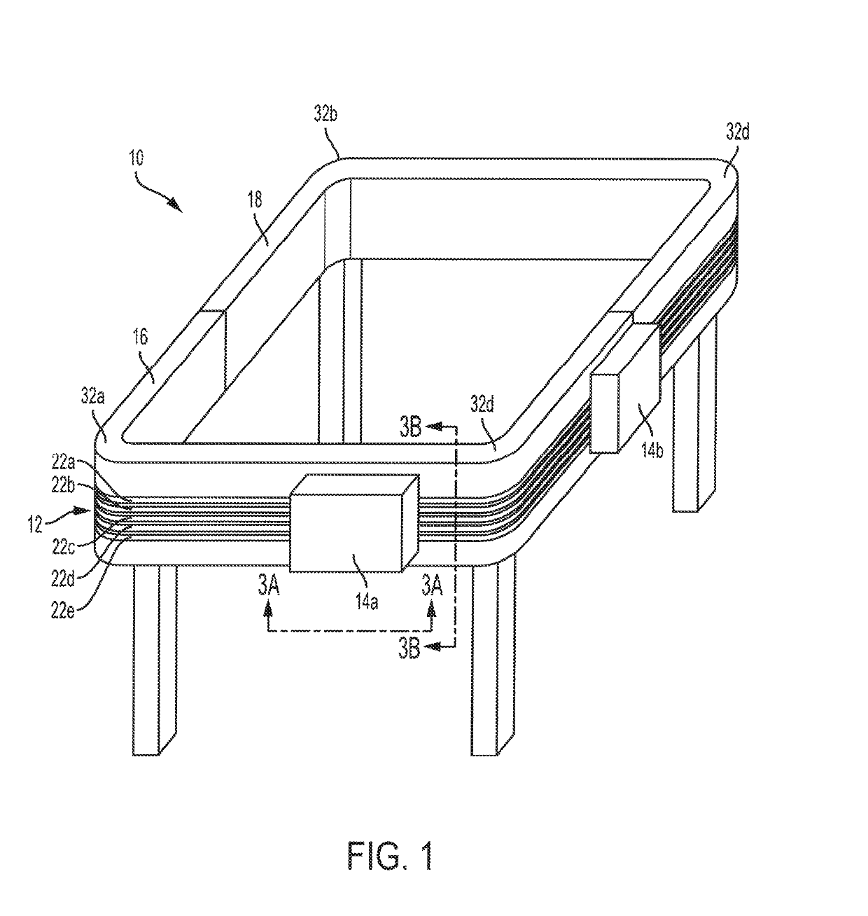
[0017]Referring to FIG. 1, an assembly machine 10 is shown in accordance with one embodiment. The assembly machine 10 may include some or all of the features and functionality described in the assembly machines 10, 100, 200, 300, 400, 500 of PCT Application Nos. PCT / US2013 / 048196 and PCT / US15 / 14996, the disclosures of which are hereby incorporated by reference to the extent that it is not inconsistent with the present disclosure. The assembly machine 10 is shown including a housing that is supported by a plurality of legs. The assembly machine 10 includes a slip track 12 disposed on the housing. One or more dispensing heads 14a, 14b may be configured to move along the slip track 12, which may create a complete circuit in the manner shown in FIG. 1. The dispensing heads 14a, 14b may ...


PUM


Abstract

A slip track includes a continuous circuitous track. The continuous circuitous track includes a layered printed circuit board. The layered printed circuit board includes a top track layer configured to supply electric power to a device having a contact element sliding across the top track layer, the layered printed circuit board further having a lower layer connected to the top track layer, the lower layer configured to supply electric power to the top track layer. The layered printed circuit board is flexible and is bent around curves in the continuous circuitous track. A method of assembly using the slip track is further disclosed.

Description

BACKGROUND OF THE DISCLOSURE[0001]This application claims priority to PCT Application No. PCT / US2016 / 038455, having a filing date of Jun. 21, 2016, entitled “Sliptrack Architecture for an Assembly Machine, System and Method,” the disclosure of which are hereby incorporated by reference.1. Technical Field[0002]This invention relates generally to a slip track architecture. More particularly, the present invention relates to a slip track architecture that may be utilized for an assembly machine or system, and methods of use thereof.2. Related Art[0003]In present slip track systems a single moving brush unit slides over a metal track. The metal track may transfer current to the moving brush unit via brushes contained on the unit and connected to internal components of the moving brush unit. The metal track in these systems is often plated with a precious metal such as hard silver, or gold, to provide minimal electrical resistance and to resist corrosion. The metal track of existing syst...

Claims


Application Information

Patent Timeline
IPC IPC(8): H05K1/18H05K13/04
CPCH05K1/189H05K13/0406H05K1/118H05K2201/058B25J5/02H05K13/0404H05K3/32
Inventor GIESKES, KOENRAAD ALEXANDER
Owner UNIVERSAL INSTR
Features
  • R&D
  • Intellectual Property
  • Life Sciences
  • Materials
  • Tech Scout
  • Unparalleled Data Quality
  • Higher Quality Content
  • 60% Fewer Hallucinations
Learn More