Positioning marker

Inactive Publication Date: 2019-06-06
NASLUND INGEMAR
View PDF0 Cites 0 Cited by
  • Summary
  • Abstract
  • Description
  • Claims
  • Application Information

AI Technical Summary

Benefits of technology

The invention is a positioning marker that can stay in place in tissue for a long time. It can be used with small needles to minimize tissue trauma. Additionally, it is cost-effective to manufacture and commonly used needles can be used with it.

Problems solved by technology

Therefore, a problem with existing solutions is that many of the larger conventional markers are, after placement in tissue, able to move much like a piston in a cylinder as e.g. blood presses against the marker.
However, such a foldable marker is more expensive to manufacture.

Method used


Image

  • Positioning marker
  • Positioning marker
  • Positioning marker

Examples


Embodiment Construction

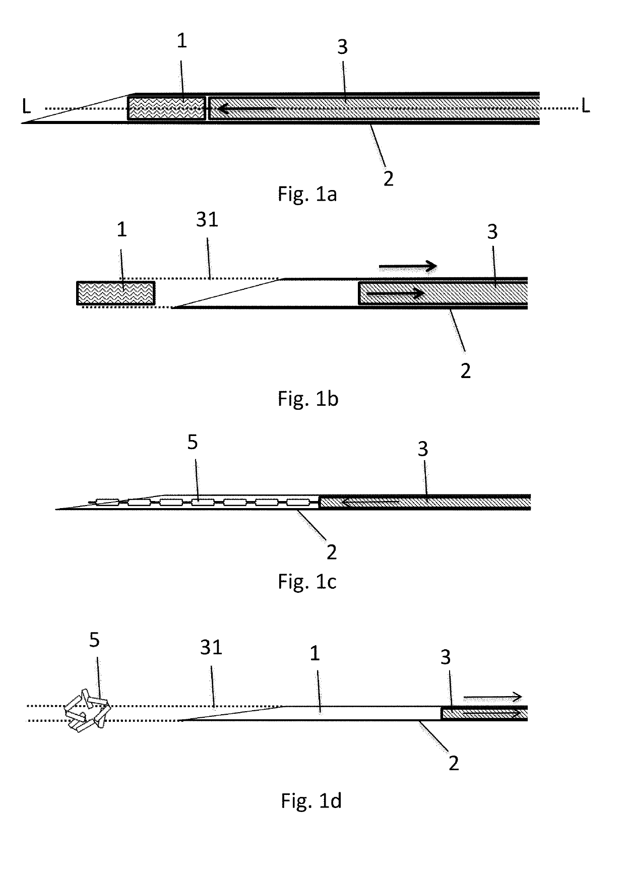
[0024]FIGS. 1a-d shows two types of commonly used conventional positioning markers used in radiotherapy, and how the marker is placed in tissue. Notably, in these and the following figures, if not specifically indicated otherwise, the left sides of the figures and the depicted devices represent the distal direction, i.e. the direction of deeper penetration into tissue, and away from the user. Thus, the right sides of the figures correspondingly show a position more proximal to a user, or closer to the skin or outside of the body, when the needle is placed into tissue. It is to be understood that the needles shown are only depicted at their distal end, and may be used to penetrate into tissue at any desired depth, i.e. a marker may be placed closed to the tissue surface, e.g. just under the skin, or deep into tissue in a body. Commonly the mandrel and / or needle may have a handle at the very proximal end (not shown), for manipulation of the relative position of the mandrel in relation...


PUM


Abstract

The present invention relates to an implantation assembly comprising a hollow needle (20) with a longitudinal axis (L) and an opening slanted at an first acute angle in relation to a plane perpendicular to said longitudinal axis (L), a mandrel (21) adapted to slide within the inside the needle along the longitudinal axis (L), and a plurality of positioning markers (10), wherein each of the plurality of markers (10) comprises an elongated marker body (11) with a proximal end (12) and a distal end (13), wherein said proximal end (12) and said distal end (13) of said marker body (11) is slanted essentially at a same second acute angle (α) in relation to the plane, wherein said plurality of positioning markers (10) are mounted distally of said mandrel (21) within said needle (20) and proximally of the distal end of said needle (20) before implantation, and said plurality of positioning markers (10) being adapted to be implanted using said hollow needle (20) and said mandrel (21), wherein the marker body (11) of each of the said plurality of positioning markers (10) is adapted to tilt and rotate in reference to the longitudinal axis (L) of the needle after exiting the slanted opening of the needle (20).

Description

FIELD OF THE INVENTION[0001]The present invention relates to a positioning marker that is intended to be inserted in tissue according to the preamble of the independent claim. The invention further relates to an implantation assembly for inserting a plurality of positioning markers.BACKGROUND OF THE INVENTION[0002]When treating cancer tumors the physician commonly prepares the treatment e.g. by planning how large the dose of the medicine shall be or how much radiation and what part of the tissue should be subjected to radiation therapy. Basis for the planning of the radiation therapy is done e.g. by using computer tomography images. Radiotherapy clinics and hospitals use MRI (magnetic resonance imaging) systems in order to improve image quality for target plotting, providing them with new possibilities to develop tailored cancer treatments and follow-ups of treatment results. Plotted tumor areas are transferred to CT (computer tomography) images which are used as a basis for dose pl...

Claims


Application Information

Patent Timeline
IPC IPC(8): A61B90/00
CPCA61B90/39A61B2090/3987A61B2090/3991A61B2090/3995A61B2090/3954A61B2090/3966
Inventor NASLUND, INGEMAR
Owner NASLUND INGEMAR
Why Eureka
Try Eureka