Eureka AIR delivers breakthrough ideas for toughest innovation challenges, trusted by R&D personnel around the world.

Ceramic Insulator

Pending Publication Date: 2019-06-06
SIEMENS ENERGY GLOBAL GMBH & CO KG
View PDF0 Cites 2 Cited by
  • Summary
  • Abstract
  • Description
  • Claims
  • Application Information

AI Technical Summary

Benefits of technology

The patent text describes a ceramic insulator for a high-voltage or medium-voltage switching system that is cost-effective to produce. The insulator consists of at least two symmetrical ceramic structural elements joined by an electrically conductive equipotential layer. The base material for the equipotential layer is a metal foil, powder, or woven fabric, which is added between the structural elements and can be incorporated during the sintering process. The length of the structural elements along their symmetry axis is between 5 mm and 50 mm. The connection between the structural elements and the equipotential layer can be monolithic or interconnected through sintering. This patent provides a simple technical solution to produce a reliable and cost-effective ceramic insulator for high-voltage or medium-voltage switching systems.

Problems solved by technology

The insulating capability of solids such as, for example, aluminum oxide ceramics, in relation to high-voltage loads is generally very high, but is limited by the finite electric strength of solids.
However, this solder method overall is very cost intensive since a high technical complexity is required in order for the corresponding vacuum tightness to be generated for the connection.

Method used


Image

  • Ceramic Insulator
  • Ceramic Insulator
  • Ceramic Insulator

Examples


Embodiment Construction

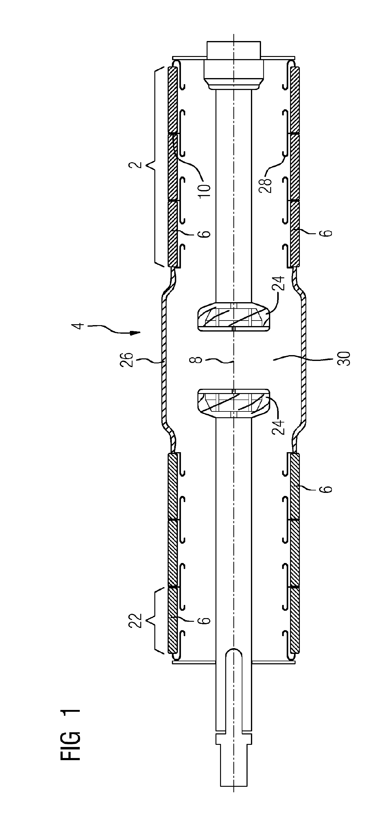
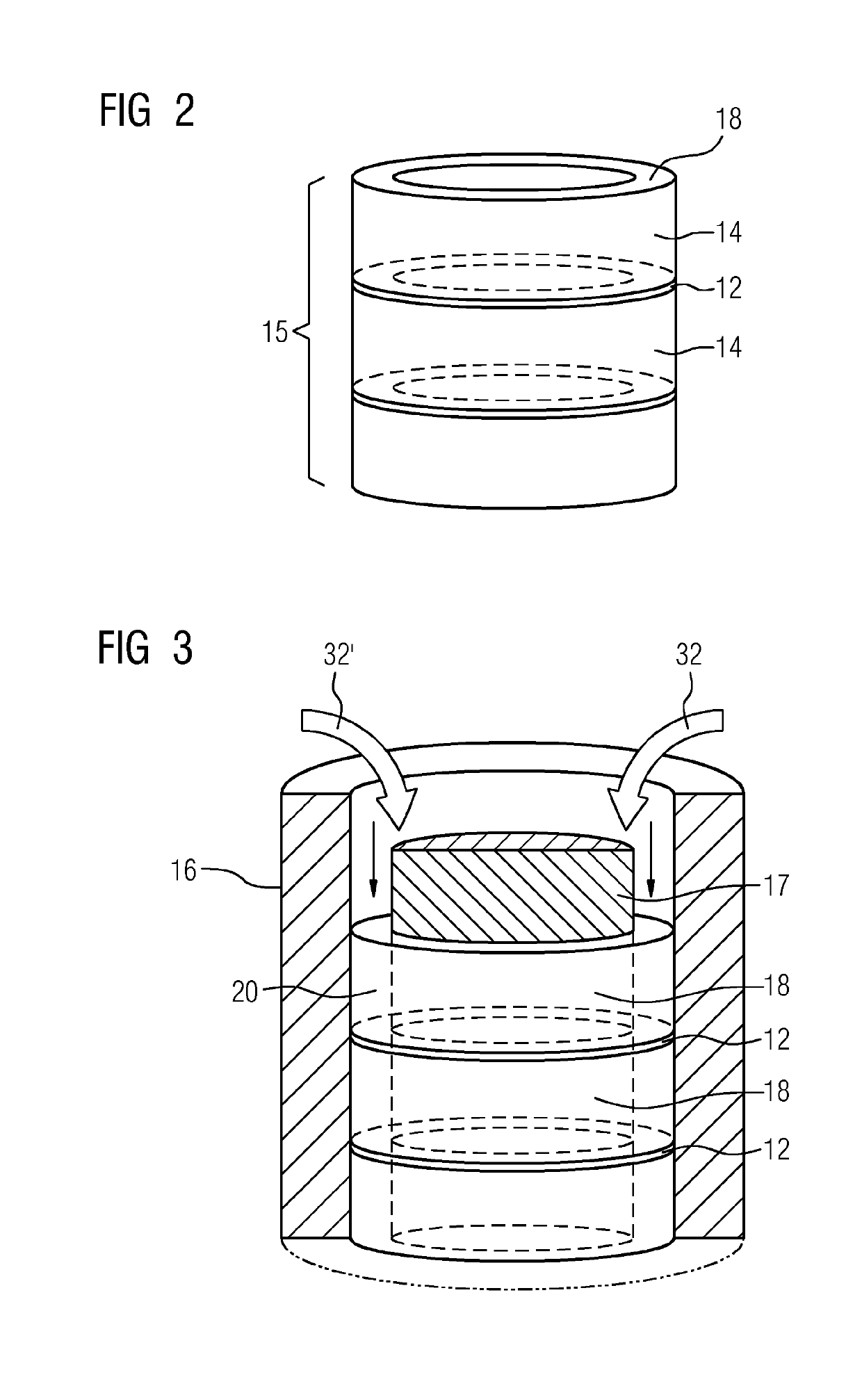
[0023]In some embodiments, a method for producing a ceramic insulator for a high-voltage or medium-voltage switching system includes at least two axially symmetrical ceramic structural elements joined along, that is to say in the direction of, the symmetry axis of the latter, that is to say in the direction of the symmetry axis of said structural elements, and an electrically conductive equipotential layer disposed between the structural elements. Along the symmetry axis, or in the direction of the symmetry axis, respectively, herein means that in practice, and in the case of preformed green bodies being used, end faces of said green bodies are joined to one another. Furthermore, the structural elements can also assume shapes which deviate from an axial symmetry, which is why the term symmetry axis in special cases is also understood to be a symmetry face. Elliptic or polygonal bodies are thus also expedient. In some embodiments, the method includes using a base material for the equ...


PUM

PropertyMeasurementUnit
Lengthaaaaaaaaaa
Lengthaaaaaaaaaa
Lengthaaaaaaaaaa

Abstract

Various embodiments include a method for producing a ceramic insulator for a high-voltage or medium-voltage switching system comprising: attaching a base material for an equipotential layer between two axially symmetrical ceramic structural elements; disposing the electrically conductive equipotential layer between the two ceramic structural elements; and joining the two ceramic structural elements to form a unitary body along a symmetry axis of a first of the two elements.

Description

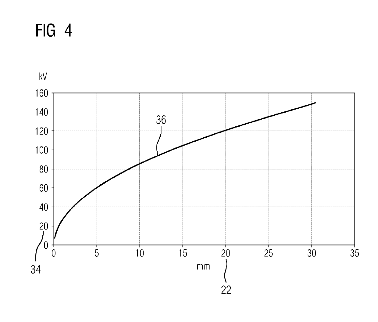
CROSS-REFERENCE TO RELATED APPLICATIONS[0001]This application is a U.S. National Stage Application of International Application No. PCT / EP2017 / 058352 filed Apr. 7, 2017, which designates the United States of America, and claims priority to DE Application No. 10 2016 208 572.7 filed May 19, 2016 and DE Application No. 10 2016 214 750.1 filed Aug. 9, 2016, the contents of which are hereby incorporated by reference in their entirety.TECHNICAL FIELD[0002]The present disclosure relates to ceramic insulators. Various embodiments may include a method for producing a ceramic insulator.BACKGROUND[0003]The insulating capability of solids such as, for example, aluminum oxide ceramics, in relation to high-voltage loads is generally very high, but is limited by the finite electric strength of solids. This also applies to high-voltage insulators, in particular ceramic insulators for medium-voltage and high-voltage vacuum interrupters. The reason therefore is the buildup of discharge within insula...

Claims


Application Information

Patent Timeline
IPC IPC(8): B32B18/00H01B19/00H01B3/12H01H33/66C04B37/00
CPCB32B18/00H01B19/00H01B3/12H01H33/66C04B37/00C04B2237/12C04B2237/78
Inventor BENKERT, KATRINHARTMANN, WERNERKOLETZKO, MARTINKOSSE, SYLVIOLANG, STEFFENRETTENMAIER, THOMASWENZEL, NORBERT
Owner SIEMENS ENERGY GLOBAL GMBH & CO KG
Why Eureka
Eureka Blog
Learn More