

Secure firmware provisioning and device binding mechanism
a technology of provisioning and device binding, which is applied in the direction of instruments, unauthorized memory use protection, computing, etc., can solve the problems of reducing the attack surface, reducing the drawback of conventional electronic devices, and copying or cloning flash memory will not yield functional firmwar
- Summary
- Abstract
- Description
- Claims
- Application Information
AI Technical Summary
Benefits of technology
Problems solved by technology
Method used
Image

Examples
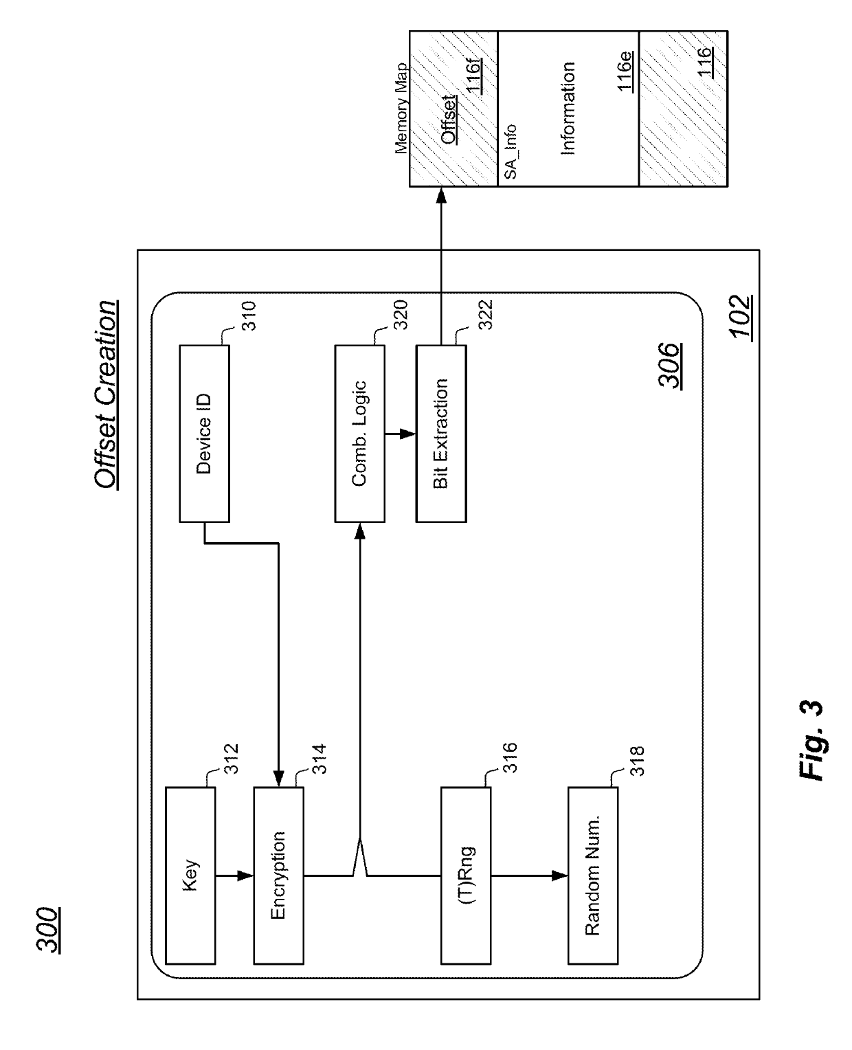
embodiment 300
[0073]FIG. 4 is another perspective 400 of the first block diagram and data flow embodiment 300 of FIG. 3 illustrating re-creation of the offset. In the discussion of FIG. 3, an example was provided wherein a firmware image was delivered to an electronic computing device 102, the device generated the third offset 116f, and the device stored the firmware image in non-volatile memory beginning at a physical address based on the third offset 116f. It is understood that when a processor 112 re-boots, the processor will often be predisposed to begin execution of instructions that are stored at a particular physical address. For this reason, it is recognized that upon a re-boot of the electronic computing device 102, and at other times, it may be necessary to re-create that third offset 116f. The perspective 400 of FIG. 4 illustrates at least one means of re-creating the third offset 116f.
[0074]In the perspective 400 of FIG. 4, an MCU 406 includes device identifier logic 410, encryption ...
embodiment 500
[0083]FIG. 6 is another perspective 600 of the second block diagram and data flow embodiment 500 of FIG. 5. The perspective 600 of FIG. 6 illustrates re-creation of the third offset 116f using an MCU 606 and a secure element 608, whose structures correspond to the MCU 506 and first secure element 508 presented in FIG. 5. Along these lines, one of skill in the art will recognize that the exemplary method presented in view of MCU 406 of FIG. 4 may be correspondingly presented in view of MCU 606 and secure element 608 of FIG. 6.
embodiment 700
[0084]FIG. 7 is a third block diagram and data flow embodiment 700 illustrating yet another structural arrangement to create the third offset 116f.
[0085]FIG. 8 is another perspective 800 of the third block diagram and data flow embodiment 700 of FIG. 7 illustrating re-creation of the third offset 116f using structures like those presented in FIG. 7.
[0086]In FIG. 7, an MCU 706 is arranged with device identifier logic 710, random number generator logic 712, encryption logic 714, secure storage logic 716, combinatorial logic 718, and bit extraction logic 720. The logic modules of FIG. 7 may respectively correspond to like logic structures of FIG. 3.
[0087]It has been recognized by the present inventors that operation of certain random number generation logic, such as a true random number generator, may be computationally expensive, time consuming, and a consumer of significant power resources. For this reason, in some cases, such as when the electronic computing device 102 is a battery...
PUM
 Abstract
Description
Claims
Application Information