Laser device
a laser device and laser technology, applied in lasers, laser details, optical resonator shape and construction, etc., can solve problems such as resolution drop
Active Publication Date: 2019-06-06
GIGAPHOTON
View PDF5 Cites 1 Cited by
- Summary
- Abstract
- Description
- Claims
- Application Information
AI Technical Summary
Benefits of technology
The patent describes a laser device that includes a laser chamber, a line narrowing optical system, a beam expander optical system, and a holding platform. These components work together to produce a high-quality beam of light that can be used in various applications. The device has technical effects including improved laser efficiency, reduced beam cross-talk, and improved laser stability. Overall, the laser device provides a more reliable and consistent beam of light for use in various industrial processes.
Problems solved by technology
Since KrF and ArF excimer laser devices each have a broad spectral linewidth in spontaneous laser oscillation or a spectral linewidth ranging from about 350 to 400 pm, the projection lens of the exposure apparatus produces chromatic aberrations in the laser light (ultraviolet light) projected on the wafer in the size-reduction projection, resulting in a decrease in resolution.
Method used
View moreImage
Smart ImageViewing Examples
Examples
first embodiment
3.2 Operation in first embodiment
3.3 Effects and advantages in first embodiment
second embodiment
4.1 Configuration in second embodiment
4.2 Operation in second embodiment
4.3 Effects and advantages in second embodiment
third embodiment
5.1 Configuration in third embodiment
5.2 Operation in third embodiment
5.3 Effects and advantages in third embodiment
Login to View More PUM
 Abstract
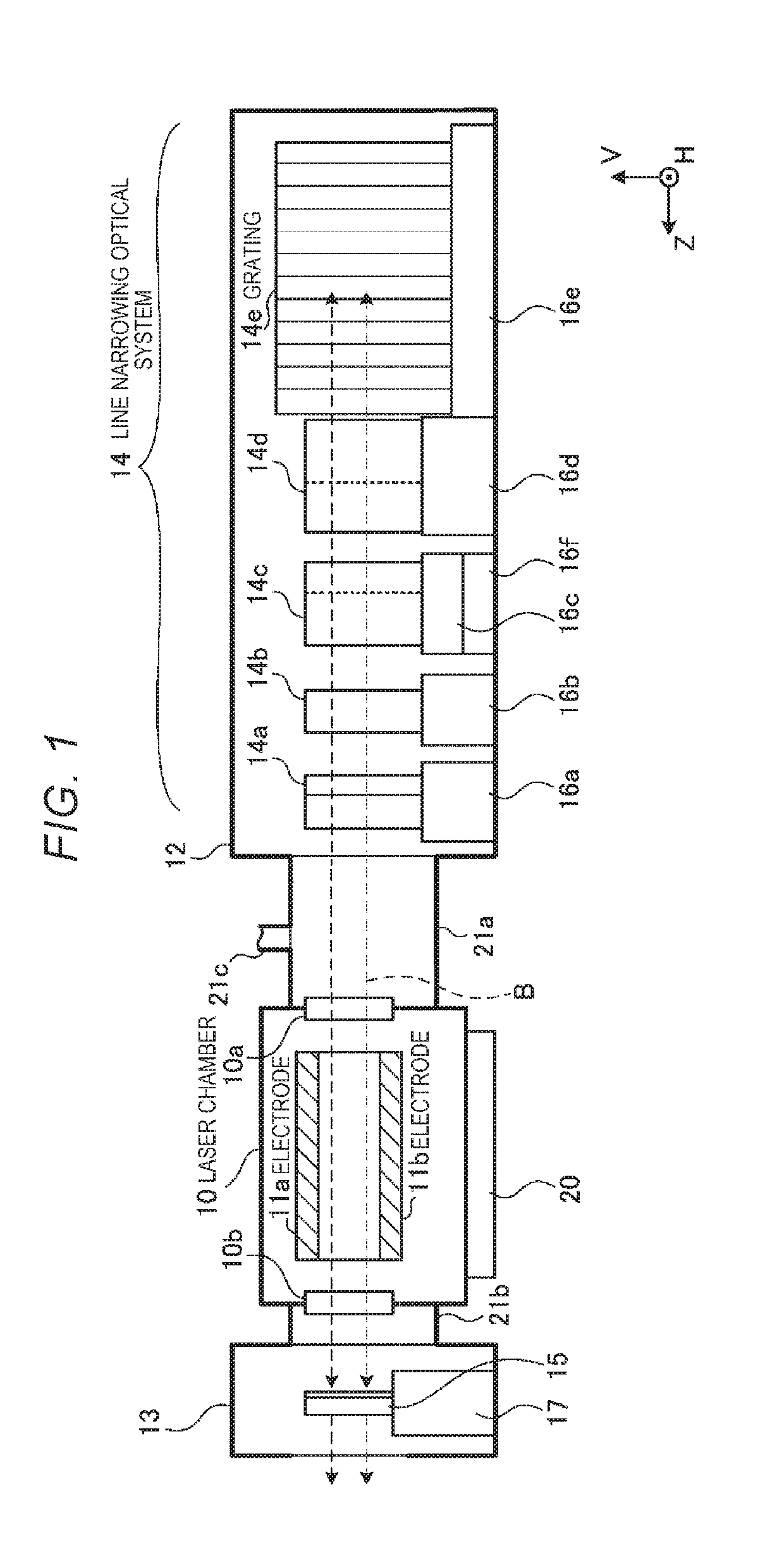
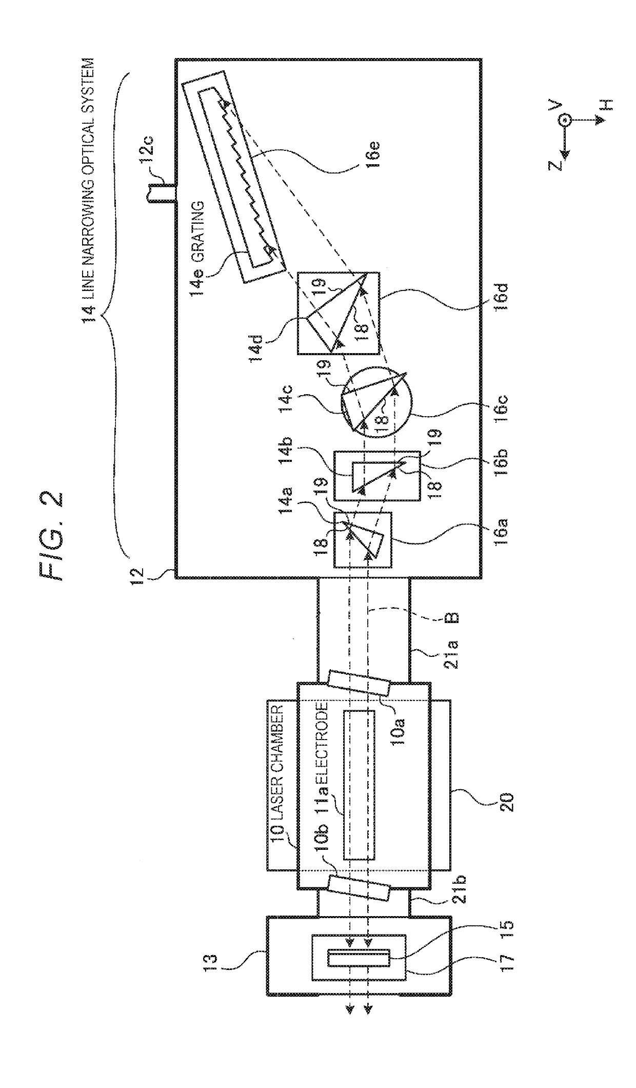
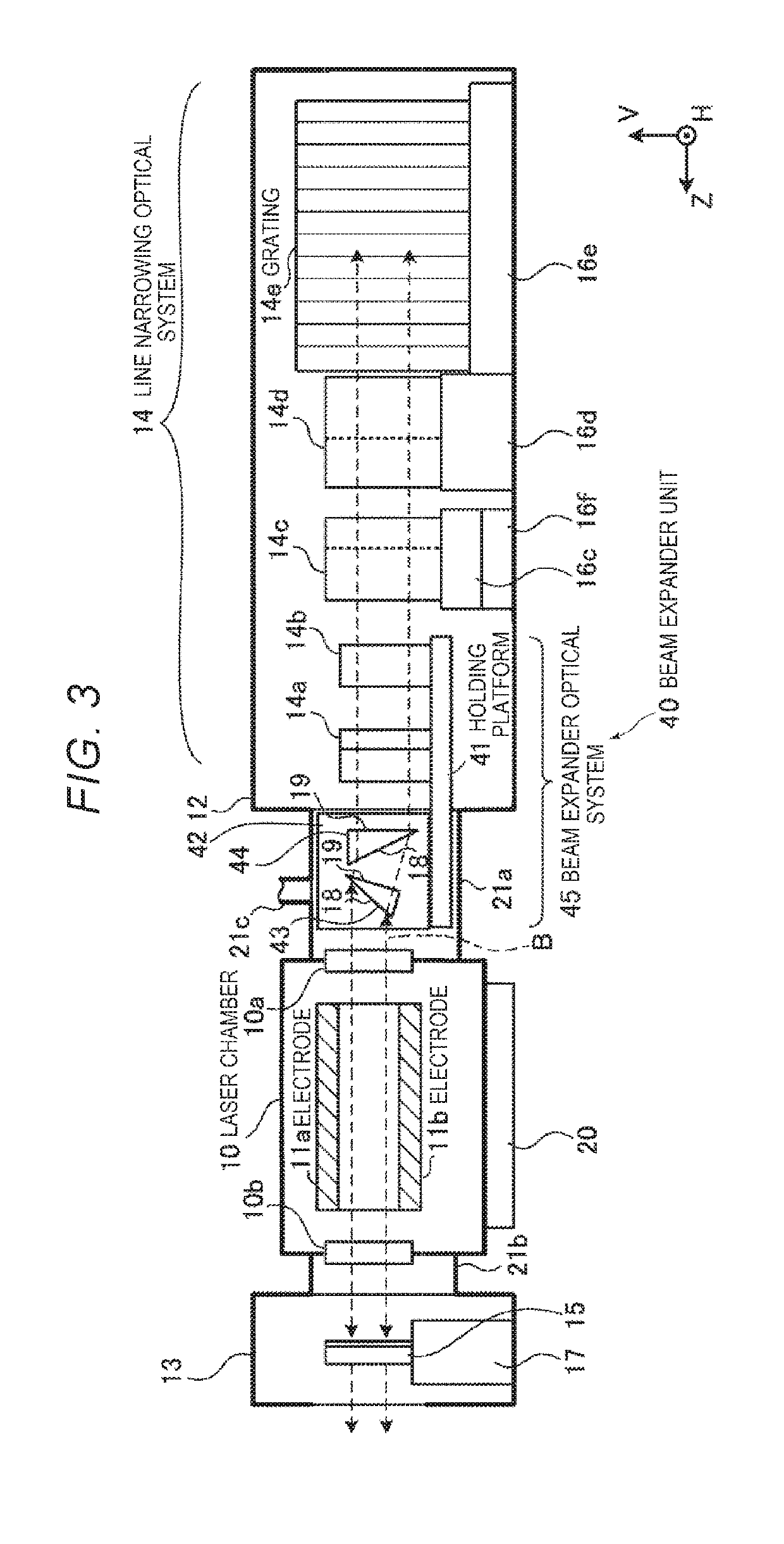
Provided is a laser device that includes a laser chamber in which a pair of discharge electrodes are disposed; a line narrowing optical system including a grating disposed in a position outside the laser chamber; a beam expander optical system that increases a diameter of a light beam, outputted from the laser chamber and traveling toward the grating, in a first direction parallel to a discharge direction between the discharge electrodes and in a second direction orthogonal to the discharge direction; and a holding platform that is formed as a component separate from the laser chamber and the grating, holds the beam expander optical system, and forms along with the beam expander optical system a beam expander unit.
Description
CROSS REFERENCE TO RELATED APPLICATIONS[0001]The present application is a continuation application of International Application No. PCT / JP2016 / 078540 filed on Sep. 27, 2016. The content of the application is incorporated herein by reference in its entirety.BACKGROUND1. Technical Field[0002]The present disclosure relates to a laser device, and particularly to a discharge-excitation-type laser device.2. Related Art[0003]As a semiconductor integrated circuit advances in terms of miniaturization and integration, improvement in resolution is required in a semiconductor exposure apparatus. A semiconductor exposure apparatus is simply referred to as an “exposure apparatus.” To achieve the improvement, the wavelength of light outputted from a light source for exposure is increasingly shortened. As the light source for exposure, a gas laser device is used in place of a conventional mercury lamp. At present, examples of the gas laser device for exposure include a KrF excimer laser device, whi...
Claims
Login to View More Application Information
Patent Timeline
 Patent Type & Authority Applications(United States)
IPC IPC(8): H01S3/08H01S3/03
CPCH01S3/08009H01S3/03H01S3/08031H01S3/08004H01S3/0971H01S3/106H01S3/2251H01S3/08H01S3/08054
Inventor MIYAMOTO, HIROTAKAWAKABAYASHI, OSAMU
Owner GIGAPHOTON
Features
- R&D
- Intellectual Property
- Life Sciences
- Materials
- Tech Scout
- Unparalleled Data Quality
- Higher Quality Content
- 60% Fewer Hallucinations
Learn More Browse by: Latest US Patents, China's latest patents, Technical Efficacy Thesaurus, Application Domain, Technology Topic, Popular Technical Reports.
© 2025 PatSnap. All rights reserved.Legal|Privacy policy|Modern Slavery Act Transparency Statement|Sitemap|About US| Contact US: help@patsnap.com


