Insert adaptor for parting off

a technology for inserting adaptors and operations, which is applied in the direction of cutting inserts, tool holders, manufacturing tools, etc., can solve the problems of increasing the overall life of the adaptor and increasing so as to increase the production cost of the adaptor, reduce the cutting depth, and increase the pocket life

Pending Publication Date: 2019-06-13
ISCAR LTD
View PDF19 Cites 3 Cited by
  • Summary
  • Abstract
  • Description
  • Claims
  • Application Information

AI Technical Summary

Benefits of technology

[0009]Previously, only two pockets were known for such adaptors. Increasing the number of pockets around a peripheral surface of an insert adaptor was previously thought disadvantageous for reducing cutting depth compared to known adaptors with two diametrically opposed pockets (due to the limitation caused during usage by the cutting edge width of an insert inside the pocket), and will increase adaptor production costs due to manufacturing of additional pocket(s), it is believed that such disadvantages can be offset by an increased pocket life which thereby increases the overall lifetime of the adaptor.
[0010]Yet a further, separate advantage, is that even though production of an insert with three or more cutting edges circumferentially spaced therearound may be simpler than a separate adaptor and insert manufacturing construction (requiring production of the pockets etc.) it has been found that comparatively long cemented carbide inserts require a greater width than metal, particularly steel, thereby increasing the material wastage in parting off operations which require relatively deep cuts. While the cemented carbide is structurally stronger, nonetheless a slightly thinner adaptor can be achieved with metal than cemented carbide, which for certain operations can be advantageous.
[0011]It has further been found that when using such insert adaptor with only a single insert only, the previously considered disadvantageous effect of reduced cut length can be eliminated.

Problems solved by technology

Increasing the number of pockets around a peripheral surface of an insert adaptor was previously thought disadvantageous for reducing cutting depth compared to known adaptors with two diametrically opposed pockets (due to the limitation caused during usage by the cutting edge width of an insert inside the pocket), and will increase adaptor production costs due to manufacturing of additional pocket(s), it is believed that such disadvantages can be offset by an increased pocket life which thereby increases the overall lifetime of the adaptor.

Method used


Image

  • Insert adaptor for parting off
  • Insert adaptor for parting off
  • Insert adaptor for parting off

Examples


Embodiment Construction

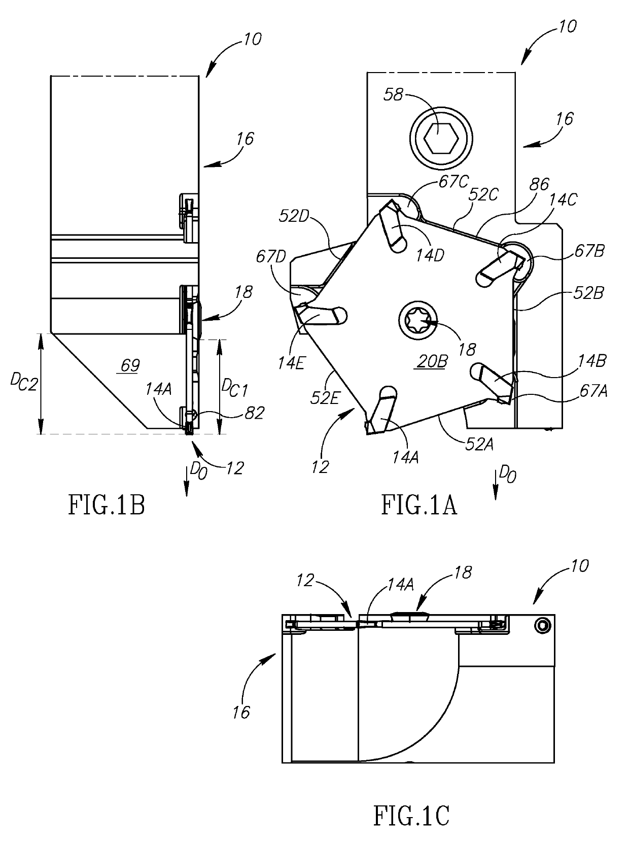
[0093]Reference is made to FIGS. 1A and 1B, illustrating a tool assembly 10 configured for parting off operations.

[0094]The tool assembly 10 can comprise an insert adaptor 12, an insert 14 (FIG. 2B; such insert designation may additionally or alternatively be designated with a suffix e.g., first, second, third and fourth pockets 14A, 14B, 14C, 14D, 14E; further designations below are also made in such manner) mounted to the insert adaptor 12, a tool holder 16, and a screw 18 used to secure the insert adaptor 12 to the tool holder 16.

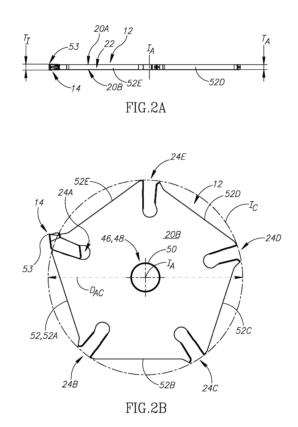
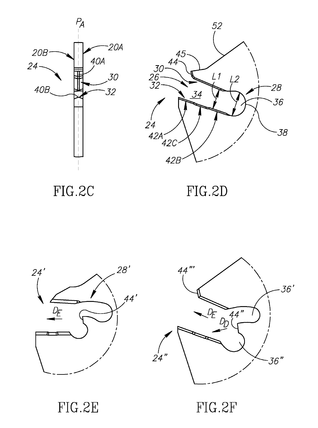
[0095]Referring now also to FIGS. 2A and 2B, the insert adaptor 12 can comprise parallel adaptor first and second sides 20A, 20B connected by an adaptor peripheral surface 22, and can have an adaptor index axis IA extending through the center of the adaptor first and second sides 20A, 20B.

[0096]The adaptor peripheral surface 22 is formed with pockets 24 (also suffixed, e.g., first, second, third, fourth and fifth pockets 24A, 24B, 24C, 24D, 24E). The poc...


PUM


Abstract

An insert adaptor for parting off including an adaptor index axis and parallel adaptor first and second sides connected by an adaptor peripheral surface which extends peripherally around the adaptor. The adaptor peripheral surface is formed with at least three pockets and bearing surfaces extending between the pockets. Each of the pockets comprises resilient upper and lower clamp surfaces.

Description

RELATED APPLICATIONS[0001]This is a Bypass Continuation of International Patent Application No. PCT / IL2017 / 050975 filed 31 Aug. 2017, which published as WO 2018 / 047162A1 and claims priority to U.S. Provisional Application No. 62 / 383,739, filed 6 Sep. 2016. The contents of the aforementioned applications are incorporated by reference in their entirety.FIELD OF THE INVENTION[0002]The subject matter of the present application relates to an insert adaptor for parting off operations, the insert adaptor comprising pockets for inserts. In particular, the subject matter of the present application relates to insert adaptors which are only rotated (i.e. indexed) about a central index axis to bring a single pocket, and hence the insert mounted in that pocket, into an operational position for machining a workpiece.BACKGROUND OF THE INVENTION[0003]EP 0 497 257 discloses a parting off device for rotating workpieces comprising an adaptor rotatably connected to a tool holder and comprising an inser...

Claims


Application Information

Patent Timeline
Patent Type & Authority Applications(United States)
IPC IPC(8): B23B29/04B23B27/08
CPCB23B29/043B23B27/08B23B2205/02B23B2250/12
Inventor HAROUCHE, DAVID BENMALKA, ASAF
Owner ISCAR LTD
Why Eureka
Try Eureka