
Orderly-micro-grooved pcd grinding wheel for positive rake angle processing and method for making same

a technology of micro-grooves and grinding wheels, which is applied in the field of grinding wheels, can solve the problems of increasing the grinding force ratio, increasing the grinding temperature, so as to improve the holding force prolong and improve the service life of the grinding wheel

Inactive Publication Date: 2020-03-05
CHANGSHA UNIVERSITY OF SCIENCE AND TECHNOLOGY
View PDF7 Cites 0 Cited by
  • Summary
  • Abstract
  • Description
  • Claims
  • Application Information

AI Technical Summary

Benefits of technology

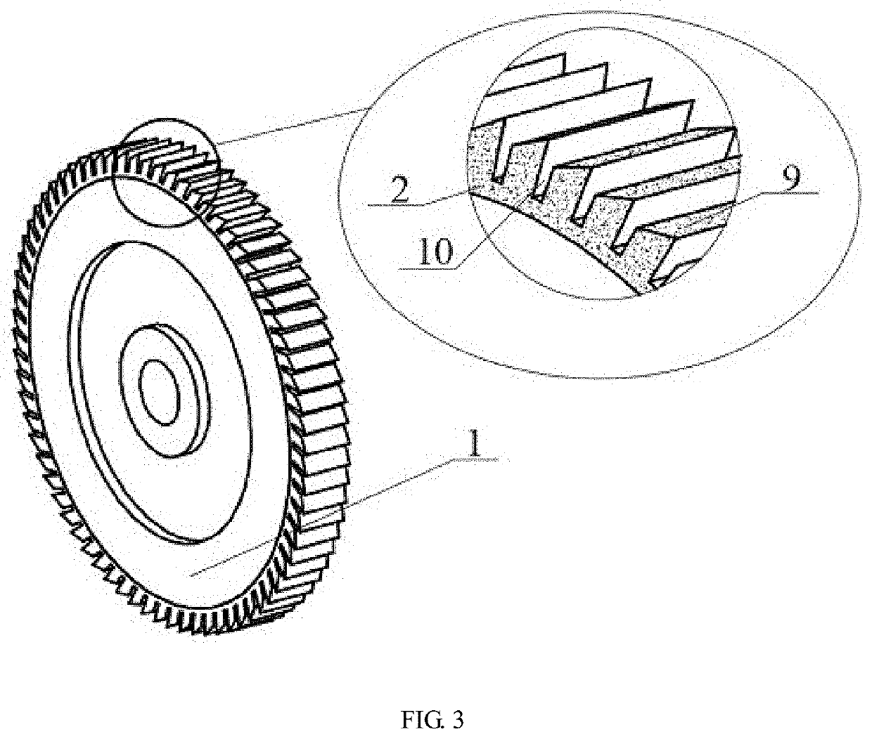
The orderly-micro-grooved PCD grinding wheel described in this patent has improved holding force, reduced grinding force ratio, increased chip-removing capacity, and improved grinding quality. It includes a PCD film, microgrooves, and micro-grinding units arranged in an ordered manner. The micro-grinding units with a positive rake angle and the microgrooves with a high depth-width ratio on the working surface of the grinding wheel can reduce the grinding force ratio, increase the chip-removing capacity, and improve the chip-holding space, which promotes the entering of the grinding fluid into the grinding zone to significantly improve the cooling effect for the grinding zone, reducing thermal damage to the grinding zone. The size and shape of the micro-grinding units on the outer circumferential surface of the grinding wheel both have a good periodicity, which makes it easier to control the relative motion relationship between the Laser-Microjet device and the grinding wheel using numerical control technology.

Problems solved by technology

However, in the traditional grinding process, abrasive grains are irregularly arranged on the working surface of the grinding wheel, and vary in geometrical shape and size, so that the abrasive grains often cut the surface of the workpiece in a large negative rake angle during the grinding process, which will increase the grinding force ratio, accelerate the conversion of grinding energy into heat and raise the grinding temperature, affecting the surface quality and grinding efficiency.
In addition, the grinding wheel also has disadvantages of small chip space and low protrusion of abrasive grains, and the grains are easy to fall off, which may easily cause a blockage at the grinding wheel and produce a local high temperature to damage the workpiece surface, and reduce the service life of the grinding wheel.
However, the single grinding unit is still operated at a zero rake angle during the grinding process, so that the grinding efficiency and the surface quality cannot be further improved.
Meanwhile, the circumferential spacing of the orderly arranged grinding units in the grinding process reaches 1 mm, which will result in a typical intermittent grinding, and the generated periodic vibrations by the grinding process may also affect the integrity of the processed surface.
However, in the process of processing large-sized diamond abrasive grains by laser, the high laser ablation temperature will inevitably cause partial graphitization on the diamond abrasive grains, affecting the positive-rake angle cutting of the abrasive grains for the workpiece surface and reducing the surface quality of the processed surface.
At the same time, the single large-sized diamond abrasive grain may fall off if it is subjected to excessive or concentrated force, which may affect the grinding efficiency and even reduce the service life of the grinding wheel.
However, since the fiber has a cross-sectional size of 0.8 mm×0.8 mm and the number of fibers per square centimeter on the surface of the tool is only 14.26, the single fiber may have a large cutting depth, making it difficult to ensure the processing precision.
Moreover, a rupture will occur if a single fiber is subjected to an excessive or concentrated force, which may affect the service life of the grinding wheel.
There are also great difficulties in the process that all the fibers are inserted into the small holes one by one and consolidated.

Method used


Image

  • Orderly-micro-grooved pcd grinding wheel for positive rake angle processing and method for making same
  • Orderly-micro-grooved pcd grinding wheel for positive rake angle processing and method for making same
  • Orderly-micro-grooved pcd grinding wheel for positive rake angle processing and method for making same

Examples


Embodiment Construction

[0040]This application will be further illustrated with reference to the embodiments and drawings.

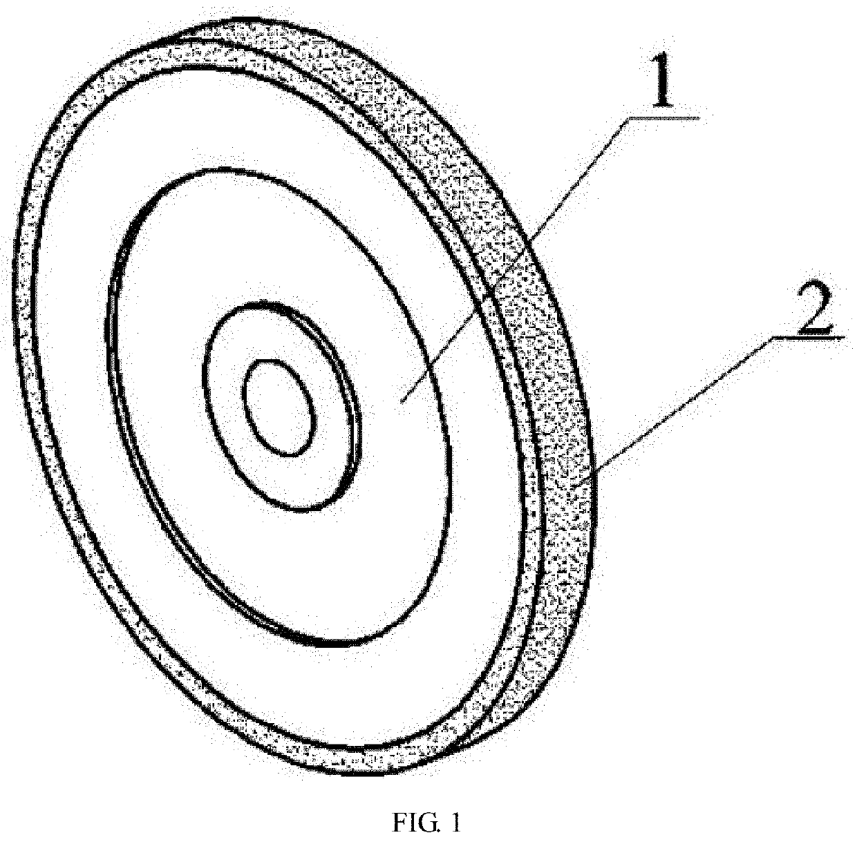
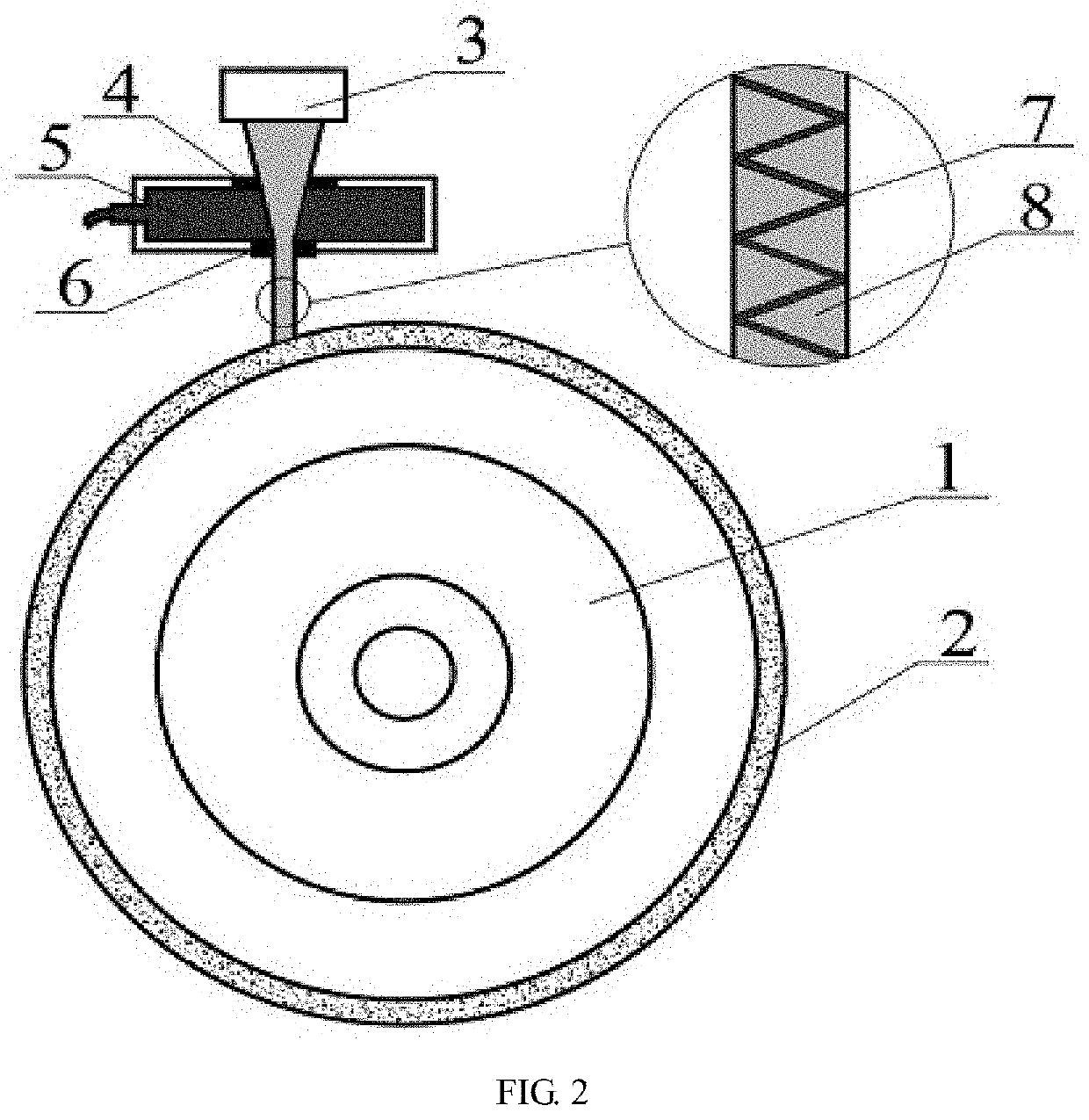
[0041]Referring to FIGS. 1-4, an orderly-micro-grooved PCD grinding wheel for positive rake angle processing includes a wheel hub 1, a PCD film 2, a plurality of micro-grinding units 9 with a positive rake angle 11 and a plurality of microgrooves 10 with a high depth-width ratio. The PCD film 2 with a thickness of 1-2 mm is deposited on an outer circumferential surface of the wheel hub 1. The microgrooves 10 which have an axial length that is equal to a thickness of the grinding wheel, a circumferential width of 20-50 μm, a depth of 500-800 μm and a depth-width ratio of 10-40:1 are provided on the outer circumferential surface of the PCD film 2. The micro-grinding unit 9 with the positive rake angle 11 is provided between two adjacent microgrooves 10, and the microgrooves 10 and the micro-grinding units 9 are both orderly arranged. When the grinding wheel is configured to grind a workpi...


PUM

PropertyMeasurementUnit
thicknessaaaaaaaaaa
depthaaaaaaaaaa
depthaaaaaaaaaa

Abstract

Disclosed are an orderly-micro-grooved PCD grinding wheel for positive rake angle processing and a preparation method thereof. A PCD film is deposited on the outer circumferential surface of a wheel hub, and a plurality of microgrooves with high depth-width ratio and micro-grinding units with positive rake angles are orderly provided on the outer circumferential surface of the entire PCD film. The method includes: depositing the PCD film on the outer circumferential surface of the wheel hub by a HFCVD technique; and manufacturing a plurality of microgrooves with a high depth-width ratio (circumferential width: dozens of micrometers; depth: hundreds of micrometers) and an axial length that is equal to the thickness of the grinding wheel and a plurality of micro-grinding units with positive rake angles on the outer circumferential surface of the entire PCD film by water-jet guided laser technique, where the micro-grinding units and the microgrooves are orderly arranged.

Description

CROSS-REFERENCE TO RELATED APPLICATIONS[0001]This application is a continuation of International Patent Application PCT / CN2019 / 090698, filed on Jun. 11, 2019, which claims the benefit of priority from Chinese Patent Application No. 201810608183.3, filed on Jun. 13, 2018. The content of the aforementioned application, including any intervening amendments thereto, is incorporated herein by reference.TECHNICAL FIELD[0002]This application relates to a grinding wheel and a preparation method thereof, and more specifically to an orderly-micro-grooved PCD grinding wheel for positive rake angle processing and a method for making the same.BACKGROUND OF THE INVENTION[0003]Grinding has been widely applied in the precision machining due to the characteristics of high processing precision and good surface quality. However, in the traditional grinding process, abrasive grains are irregularly arranged on the working surface of the grinding wheel, and vary in geometrical shape and size, so that the...

Claims


Application Information

Patent Timeline
Patent Type & Authority Applications(United States)
IPC IPC(8): B24D5/02B24D18/00
CPCB24D5/02B24D18/00B24D7/06B24D18/009B24D5/06B24D5/10B24D5/123
Inventor MAO, CONGYIN, LAIRONGZHONG, YUJIEHU, YONGLECAI, PEIHAOZHANG, MINGJUNJIANG, YIFENG
Owner CHANGSHA UNIVERSITY OF SCIENCE AND TECHNOLOGY
Learn More