Motor unit

Active Publication Date: 2019-06-13
NIDEC CORP
View PDF7 Cites 6 Cited by
  • Summary
  • Abstract
  • Description
  • Claims
  • Application Information

AI Technical Summary

Benefits of technology

[0004]In view of the above problem, example embodiments of the present disclosure provide motor uni

Problems solved by technology

Therefore, the distance between the central axis of the differential and the central axis of the motor i

Method used


Image

  • Motor unit
  • Motor unit
  • Motor unit

Examples


Example

[0030]Hereinafter, motors according to embodiments of the present disclosure will be described with reference to the accompanying drawings. Note that the scope of the present disclosure is not limited to the embodiments described below, but includes any modification thereof within the scope of the technical idea of the present disclosure. Also note that scales, numbers, and so on of members or portions illustrated in the following drawings may differ from those of actual members or portions, for the sake of easier understanding of the members or portions.

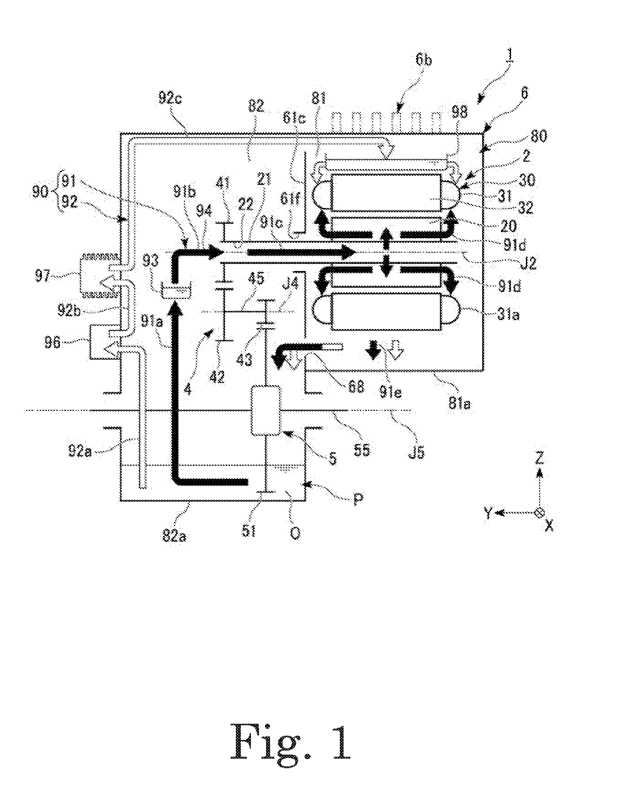
[0031]The following description will be made with the direction of gravity being defined on the basis of positional relationships in the case where a motor unit 1 is installed in a vehicle on a horizontal road surface. In addition, in the drawings, an xyz coordinate system is shown appropriately as a three-dimensional orthogonal coordinate system. In the xyz coordinate system, a z-axis direction corresponds to a vertical direction (...


PUM


Abstract

A motor unit includes a motor including a rotor, a reduction gear including an intermediate gear to rotate about an intermediate axis, a differential including a ring gear arranged to rotate about a differential axis, a housing, oil in a vertically lower region of a housing space, and an oil passage to feed the oil to the motor. At least a portion of the ring gear is lower than a liquid surface of the oil in the vertically lower region of the housing space. A motor axis, the intermediate axis, and the differential axis to extend in parallel with one another in a horizontal direction. Each of the intermediate axis and the differential axis is lower than the motor axis. A line segment imaginarily joining the motor axis and the intermediate axis, a line segment imaginarily joining the intermediate axis and the differential axis, and a line segment imaginarily joining the motor axis and the differential axis when viewed in an axial direction of the motor axis are defined as first, second, and third line segments, respectively. The first line segment extends substantially along a vertical direction. The second line segment extends substantially along a horizontal direction.

Description

BACKGROUND OF THE INVENTION1. Field of the Invention[0001]The present invention relates to a motor unit.2. Description of the Related Art[0002]There is known a motor that allows an oil gathered in a gear case and scraped up through rotation of a gear to be introduced into a flow passage in an interior of a shaft thereof.[0003]In the case of the above known structure, a central axis of the motor, a central axis of a reduction gear, and a central axis of a differential are arranged in the order named along a horizontal direction when viewed in an axial direction. Therefore, the distance between the central axis of the differential and the central axis of the motor is so large that an oil scraped up by the differential cannot be easily fed to a gear of the motor shaft.SUMMARY OF THE INVENTION[0004]In view of the above problem, example embodiments of the present disclosure provide motor units each being capable of efficiently feeding an oil to tooth surfaces of gears around various axes...

Claims


Application Information

Patent Timeline
IPC IPC(8): F16H57/04H02K7/116H02K9/19
CPCF16H57/0424H02K7/116H02K9/19F16H57/0427F16H57/0441F16H57/0452F16H57/0457F16H57/0478F16H57/0493B60K1/00F16H63/3425F16H57/0417F16H57/0423F16H57/043F16H57/045F16H57/0476F16H57/0483B60K2001/001B60Y2306/03B60K2001/006B60K11/02
Inventor ISHIKAWA, YUKIYAMAGUCHI, YASUOMIGITA, TAKAYUKI
Owner NIDEC CORP
Why Eureka
Try Eureka