Coolant distribution unit

a technology of cooling unit and cooling fan, which is applied in the direction of electrical equipment, electrical apparatus, electrical apparatus contruction details, etc., can solve the problems of increasing the processing power of electronic computing devices, large amount of generated heat, and inability to meet the requirements of heat dissipation, so as to increase the application value of cooling unit and optimize the energy utilization of cooling uni

Inactive Publication Date: 2019-06-13
AURAS TECH
View PDF4 Cites 5 Cited by
  • Summary
  • Abstract
  • Description
  • Claims
  • Application Information

AI Technical Summary

Benefits of technology

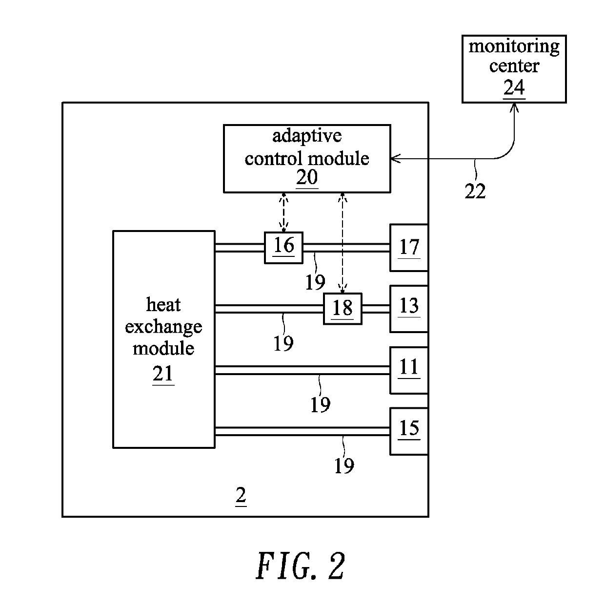
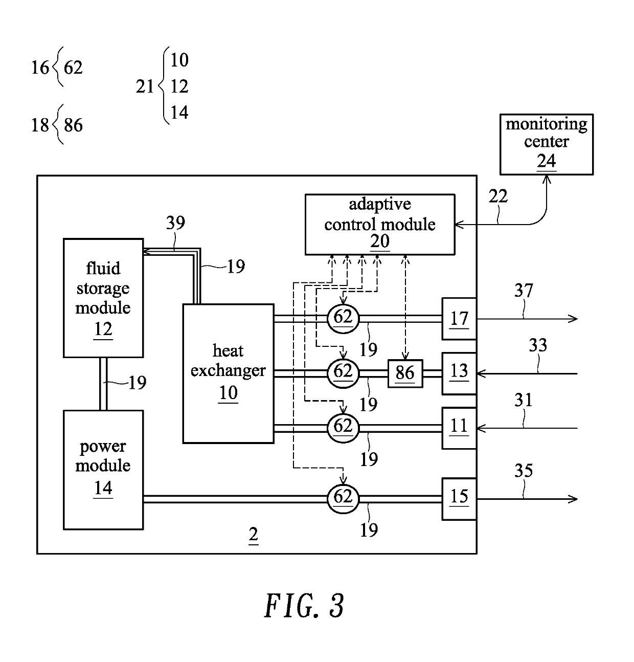
[0011]For increasing the application value of the coolant distribution unit, the present invention provides a novel coolant distribution unit. The coolant distribution unit has the function of adaptively adjusting the flowrate of a working fluid. Consequently, the energy utilization of the coolant distribution unit is optimized.

Problems solved by technology

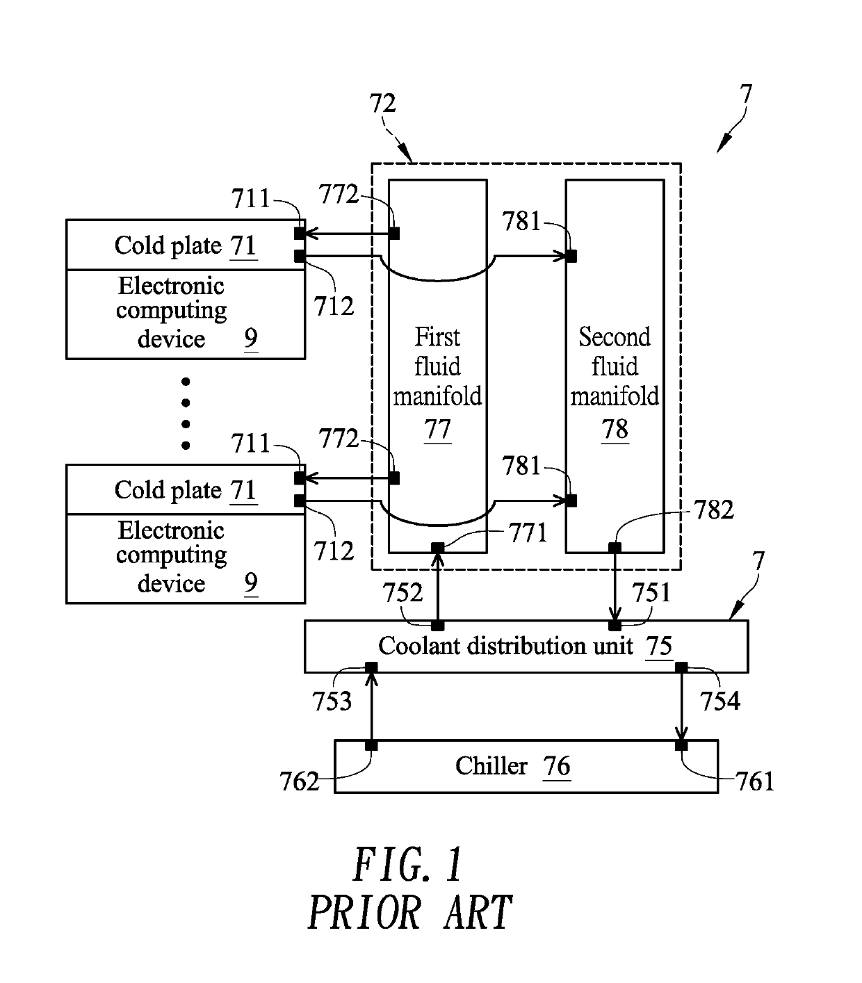
With the advent of big data and the Internet era, the processing power of the electronic computing device is increasing and the amount of the generated heat is large.
Even if the rack cabinets comply with the same specifications, the heat dissipation demands are not always identical.
Under this circumstance, the heat dissipating capacities of some rack cabinets in some abnormal situations are insufficient.

Method used


Image

  • Coolant distribution unit
  • Coolant distribution unit
  • Coolant distribution unit

Examples


Embodiment Construction

[0022]For illustration, the structures, organizations or components of the coolant distribution unit shown in the drawings of the present invention are in scale with the elements of the practical product. According to the requirements of descriptions, the components may be scaled up or scaled down in an unequal proportion. The implementations of the coolant distribution unit not limited by the drawings.

[0023]In this context, the working fluid is the fluid that is used in a heat exchanger and is in the liquid sate in the normal temperature. Generally, water is the widely-used fluid. It is noted that the example of the working fluid is not restricted. In other embodiments, the working fluid is aqueous solution or other organic solution. At different temperatures, the working fluid has the corresponding vapor-liquid equilibrium pressures. The working fluid retained in, transferred through or moved across the piping channel or the overall system is a liquid-state fluid. In practice, the...


PUM


Abstract

A coolant distribution unit includes plural fluid inlets, plural fluid outlets and a piping channel. The piping channel is connected with the fluid inlets and the fluid outlets. The sensed temperature or the measured pressure or flowrate of a working fluid in the piping channel is transmitted to an adaptive control module. The sensed temperature or the measured pressure or flowrate is further transmitted to an external monitoring center. Consequently, the supervisor of the monitoring center can manage and control the operating situation of the coolant distribution unit.

Description

CROSS-REFERENCE TO RELATED APPLICATION[0001]This application claims priority to U.S. Provisional Patent Application No. 62 / 597,963 filed Dec. 13, 2017, the contents of which are incorporated herein by reference.FIELD OF THE INVENTION[0002]The present invention relates to a field of a coolant distribution unit (CDU), and more particularly to a coolant distribution unit for a machine room / rack cabinet liquid cooling system.BACKGROUND OF THE INVENTION[0003]With the increasing development and popularization of science and technology, various electronic computing devices such as network storage devices or servers have been essential parts of people's daily lives. Generally, these electronic computing devices are stored in a rack cabinet that is made of cold-rolled steel or alloy. Consequently, these electronic computing devices are protected from electromagnetic interference and arranged in an orderly and neat manner. Moreover, the electronic computing devices in the rack cabinet can be ...

Claims


Application Information

Patent Timeline
Patent Type & Authority Applications(United States)
IPC IPC(8): F28F27/02
CPCF28F27/02H05K7/20781H05K7/20836
Inventor CHEN, CHIEN-ANFAN, MU-SHUCHEN, CHIEN-YU
Owner AURAS TECH
Why Eureka
Try Eureka