Motor and Actuator Unit

Active Publication Date: 2019-06-13
TOKYO PARTS IND CO LTD
View PDF6 Cites 0 Cited by
  • Summary
  • Abstract
  • Description
  • Claims
  • Application Information

AI Technical Summary

Benefits of technology

This patent is about a new type of motor that uses a special magnet rotor with gears. This design allows the magnet to be securely held in place and maintains its alignment with other components. In one aspect, the patent describes a mechanism that reduces the speed of the rotor, which is made up of small teeth. The technical effect of this design is a more reliable and efficient motor that can achieve smooth and symmetrical motion.

Problems solved by technology

However, the structure of the permanent magnet rotor described in Japanese Patent Laid-Open Publication No. 2015-524244 does not allow the member provided with the rotary gear to constrain the permanent magnet in the axial direction.
Therefore, in order to constrain the movement of the permanent magnet in the axial direction, an adhesive or the like must be separately used, which not only increases the number of work steps during assembly, but also presents a problem in that the reliability of fixation with an adhesive is low.
However, there is a problem in that one side of the ring magnet is locally cut away for the purposes of constraining the movement of the ring magnet in the circumferential direction, which detracts from the symmetry of magnetization of the ring magnet, and adversely affects the rotational drive force.
Furthermore, although the locking claw that locks on one side of the ring magnet in the axial direction is arranged at the forward end of a flexible cantilevered beam, by way of a slit provided in the core, this cantilevered beam does not have a structure capable of imparting a biasing force to the ring magnet in the radially outward direction.
Therefore, there is likely to be play between the ring magnet and the core, due to the dimensional tolerances of the ring magnet and the core, and as a result, it is likely that fixation with adhesive will be necessary.

Method used


Image

  • Motor and Actuator Unit
  • Motor and Actuator Unit
  • Motor and Actuator Unit

Examples


embodiment

Fourth Exemplary Mode of Embodiment

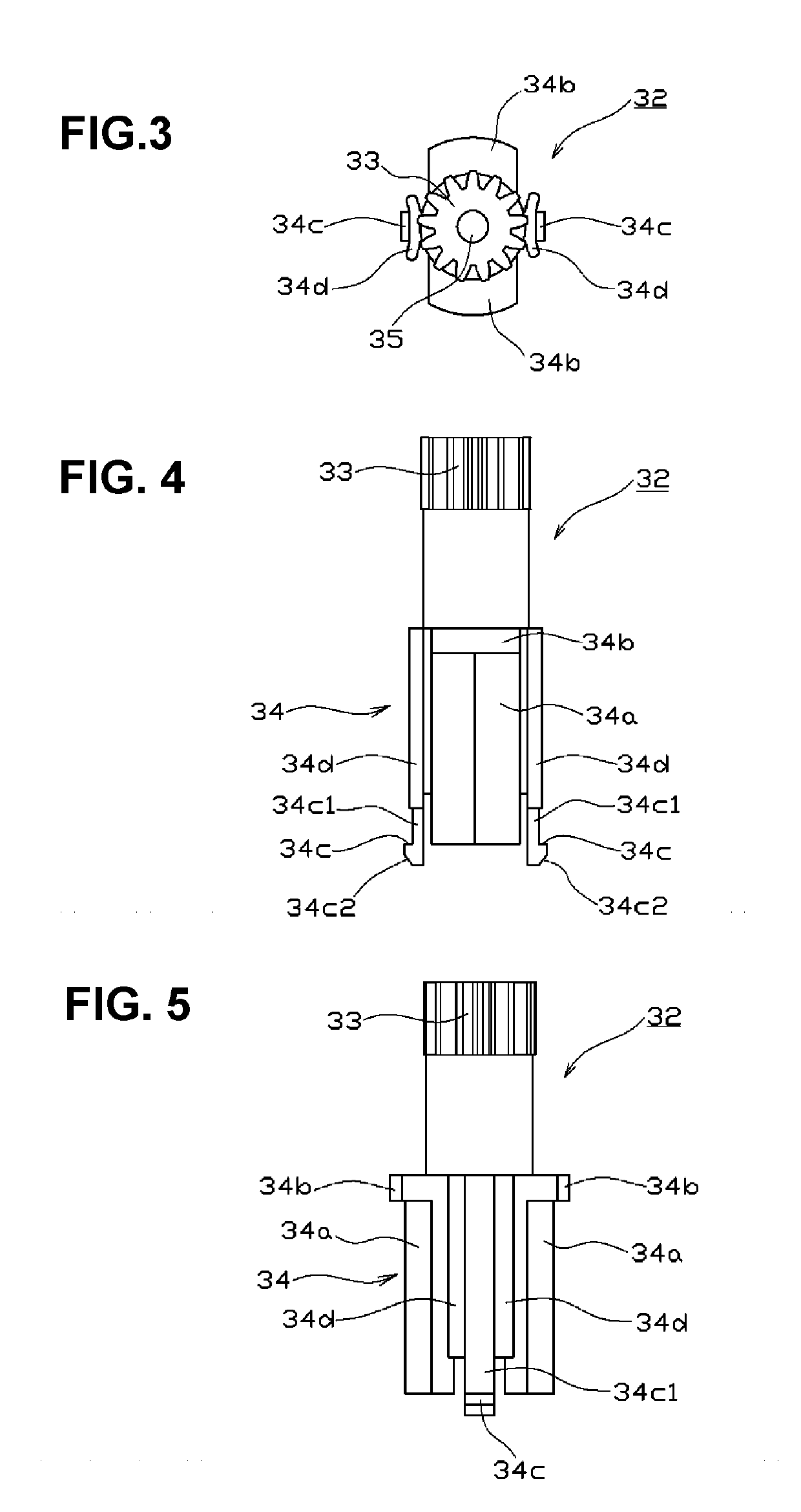
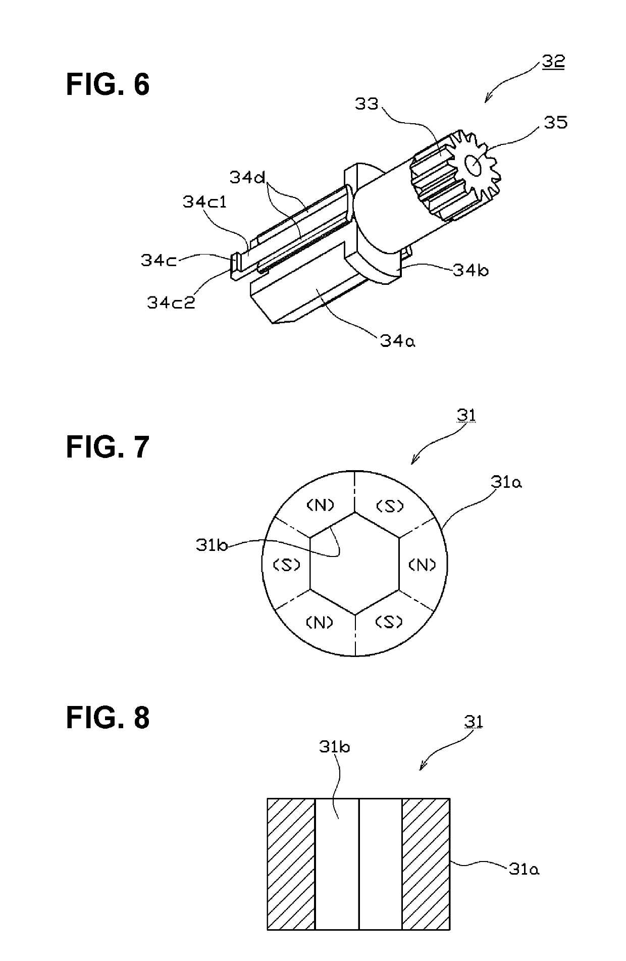
[0072]A fourth exemplary mode of embodiment of the present invention will be described with reference to FIGS. 18 and 19. Note that, in these figures, constituent parts that are the same as in the first exemplary mode of embodiment are given the same reference numerals, and redundant description thereof is forgone. In this example, the major difference from the first exemplary mode of embodiment is the structure for the axial-direction constraint of the permanent magnet 31 by the gear member 32. Specifically, in the first exemplary mode of embodiment, the upper axial-direction constraining part 34b is formed in the shape of flanges but, in this example, the outer diameter of the pinion 33 is made larger than the inner peripheral face 31b of the permanent magnet 31, such that the outer edge portion of the lower surface of the pinion 33 is used as the upper axial-direction constraining part 34b. Note that the elastic pieces 34d are arranged in the sp...


PUM


Abstract

A motor comprises: a shaft; a permanent magnet rotor in which a permanent magnet and a gear member 32 are united; and a stator, arranged facing the permanent magnet. The gear member 32 has a pinion 33 and a mounting part 34. The mounting part 34 has: a circumferential-direction constraining part 34a, which constrains the circumferential movement of the permanent magnet; axial-direction constraining parts 34b, 34c, which abut both the top and bottom surfaces of the permanent magnet, so as to constrain the axial movement of the permanent magnet; and a plurality of elastic pieces 34d that apply a radially outward biasing force to the inner peripheral face of the permanent magnet.

Description

BACKGROUND OF THE INVENTION[0001]The present invention relates to a motor having a permanent magnet rotor, and to an actuator unit provided with the same.[0002]Actuators are known which, for example, automatically open and close grille shutters, in order to feed in air around an engine or a radiator for cooling, and to release hot air inside the hood, in accordance with the travelling state of a vehicle and the warming state of the engine.[0003]In terms of such actuators, for example, Japanese Patent Laid-Open Publication No. 2015-524244 discloses a grille shutter drive device including: motor unit, which generates a drive force that drives a grille shutter, a control unit, which controls the generation of the drive force of the motor unit; and a coupling unit, which applies the drive force of the motor unit to the grille shutter. In this grille shutter drive device, a permanent magnet rotor is used, in which a permanent magnet is disposed on the outer peripheral face of a member pr...

Claims


Application Information

Patent Timeline
IPC IPC(8): H02K15/03B60K11/08H02K7/00H02K7/08H02K7/116
CPCH02K15/03B60K11/085H02K7/003H02K7/083H02K7/116H02K1/2733H02K1/30H02K5/1677H02K7/086Y02T10/88
Inventor NISHIDATE, MASAHIRO
Owner TOKYO PARTS IND CO LTD
Why Eureka
Try Eureka