Portable collapsable storage bin and unloading system

a storage bin and collapsible technology, applied in the field of collapsible storage bins, can solve the problems of not being well suited to portability, and being difficult to move, etc., and achieve the effect of reducing the lateral width

Active Publication Date: 2019-06-20
543077 ALBERTA LTD
View PDF0 Cites 3 Cited by
  • Summary
  • Abstract
  • Description
  • Claims
  • Application Information

AI Technical Summary

Benefits of technology

[0016]According to one embodiment, the base frame may be supported on wheels for rolling movement along the ground surface in a forward rolling direction. In this instance, the base frame may be operative to be reduced in lateral width perpendicular to the forward rolling direction in the transport position relative to the working position. The base f

Problems solved by technology

In some instances, a storage bin or silo is only required for temporary use at a given location; however, a typical storage bin is large in size and includes a rigid cylindrical side wall of large diameter so as to be difficult to transport between different locations.
Although some attempts have

Method used


Image

  • Portable collapsable storage bin and unloading system
  • Portable collapsable storage bin and unloading system
  • Portable collapsable storage bin and unloading system

Examples


first embodiment

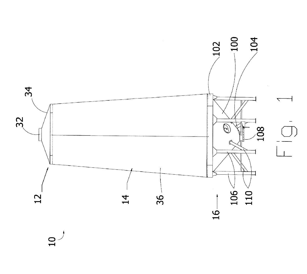
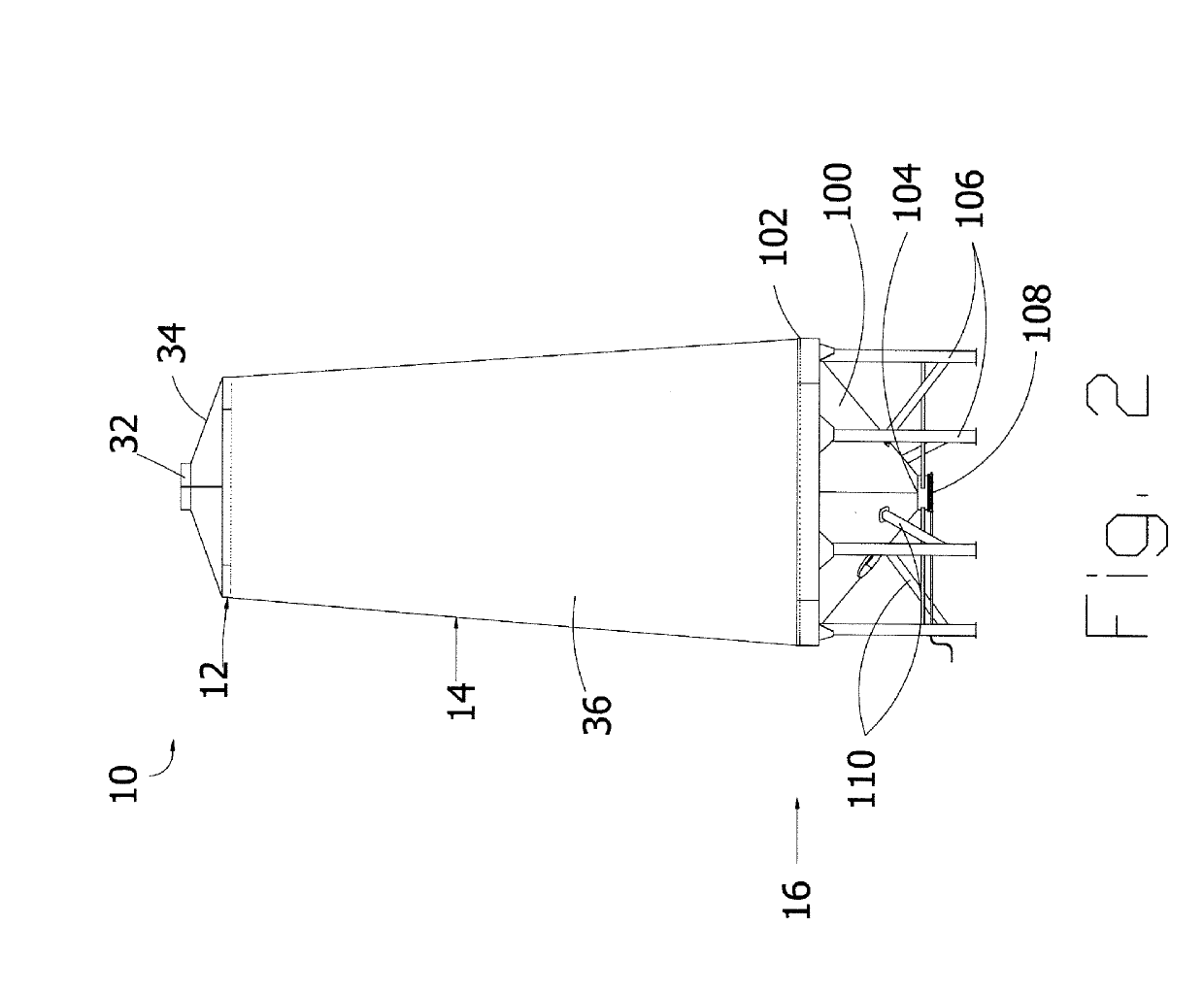
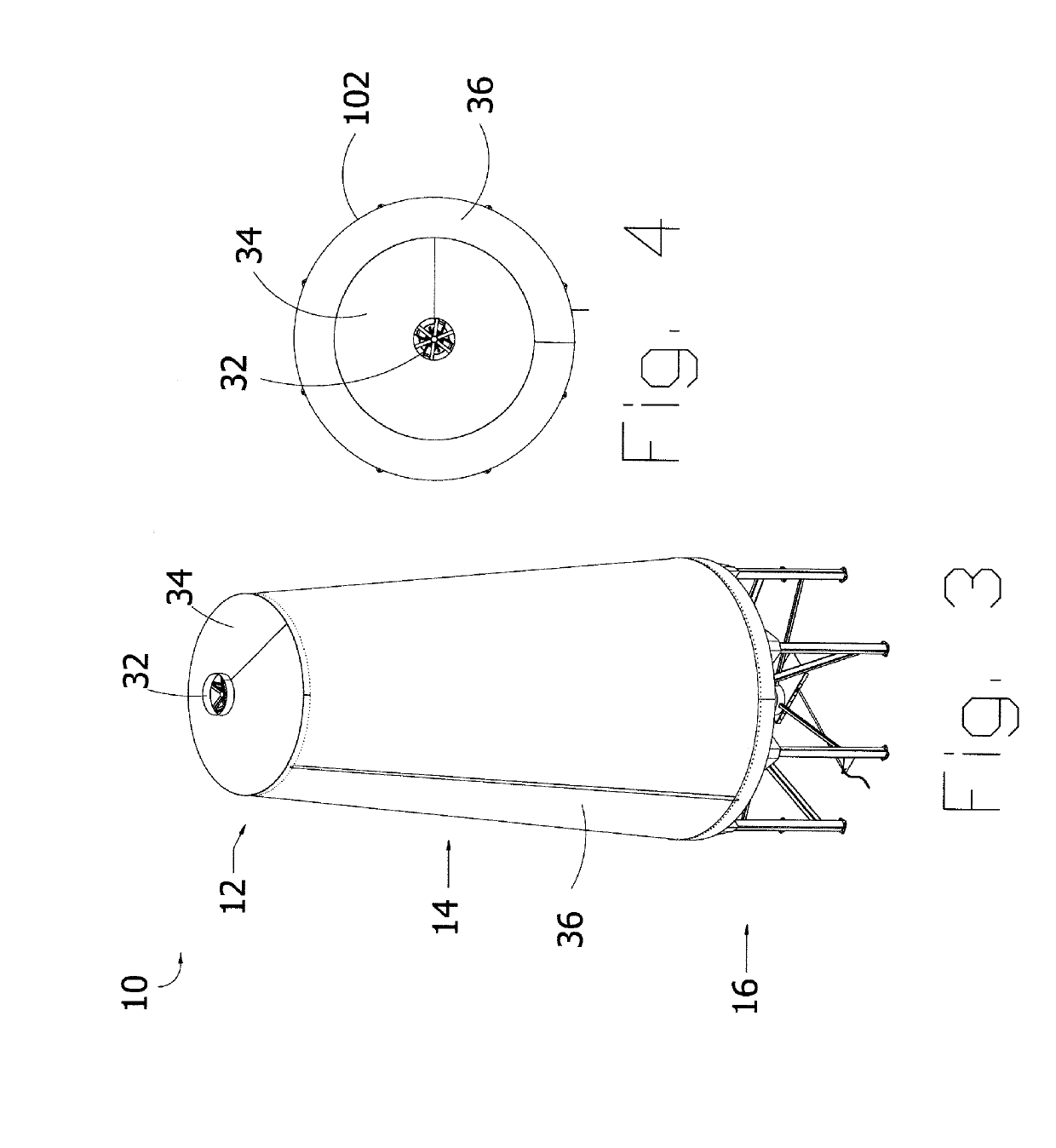
[0081]Turning now more particularly to the first embodiment, the base frame 16 in this instance defines a rigid hopper cone 100 having a rigid conical wall which tapers downwardly and inwardly from an upper perimeter edge 102 which is circular and lies in a horizontal plane, to a central discharge opening 104 centrally located at the bottom end of the cone so as to be supported at a location spaced upwardly above the ground surface when the base frame is engaged upon the ground surface. The base frame in this instance further includes a plurality of support members 106 comprising vertical leg members extending downwardly from the upper perimeter edge 102 of the cone at evenly spaced apart positions about the full circumference of the cone. The support members 106 are greater in height than the cone 100 to support the central discharge spaced above the ground when the bottom ends of the support members are engaged upon the ground.

[0082]The bottom edge of the wall portion 36 of the en...

second embodiment

[0088]Turning now more particularly to the second embodiment, the base frame 16 in this instance includes a flat bottom which is arranged to be engaged on a ground surface in the working position. A main frame portion of the base frame is primarily defined by two side rails 218 which extend substantially a full length of the base frame in a longitudinal direction so as to be parallel and spaced apart from one another in a lateral direction along opposing sides of the main frame portion. A rear crossbar 220 is connected between the rear ends of the two side rails 218. Two hitch arms 222 are connected to the front ends of the two side rails respectively such that the two hitch arms extend forwardly and inwardly towards one another to be coupled at a forward end where a hitch 224 is mounted which is suitable for connection to a towing vehicle. A front jack 226 is coupled adjacent to the hitch 224 at the front end of the hitch arms 222 so as to be operable to selectively lift the front ...


PUM


Abstract

A portable storage bin includes a base frame on the ground and a bin support frame operable relative to the base frame between a working position and a transport position which is reduced in height relative to the working position, and a storage envelope supported on the bin support frame to define a storage chamber for storing particulate material therein in the working position of the bin support frame in which the storage envelope is collapsible with the bin support frame from the working position to the transport position. The bin support frame has an upper frame portion from which the storage envelope is suspended in the working position and a central support post which is extendable in height between the upper frame portion and the base frame for raising the envelope from the transport position to the working position.

Description

[0001]This application claims foreign priority benefits from Canadian Patent Application No. 2,989,632, filed Dec. 20, 2017.FIELD OF THE INVENTION[0002]The present invention relates to a particulate material storage bin, for example a grain silo, which can be collapsed for transport. More particularly, the present invention relates to a collapsible storage bin including a rigid frame structure supporting a flexible storage envelope thereon.BACKGROUND[0003]It is common to store various materials including grain, granular fertilizer, and other particulate materials in grain storage bins or silos. In some instances, a storage bin or silo is only required for temporary use at a given location; however, a typical storage bin is large in size and includes a rigid cylindrical side wall of large diameter so as to be difficult to transport between different locations. Although some attempts have been made in the prior art to provide a portable storage bin, such bins are either small and limi...

Claims


Application Information

Patent Timeline
IPC IPC(8): B65D88/16A01F25/14B65D88/30B65D88/52
CPCB65D88/1631A01F25/14B65D88/30B65D88/52E04H7/24A01F12/60B65D88/005B65D88/22
Inventor THIESSEN, LONNYTHIESSEN, ROLAND
Owner 543077 ALBERTA LTD
Why Eureka
Try Eureka