Improved Reversible Pump-Turbine Installation

Active Publication Date: 2019-06-20
BHE TURBOMACHINERY LLC
View PDF0 Cites 11 Cited by
  • Summary
  • Abstract
  • Description
  • Claims
  • Application Information

AI Technical Summary

Benefits of technology

[0014]In accordance with a further aspect of the invention a reversible pump turbine runner or pump impeller is provided that imparts to the flow an upward velocity component. This upward velocity component allows the flow to proceed directly up through the diffuser or a guide vane-diffuser combination in the case of a reversible pump-turbine, or directly to a diffuser (stator) stage in the case of a multi-stage pump

Problems solved by technology

Positioning of the runner below tailwater has heretofore required a deep and expensive excavation regardless of machine size and rating.
The expense of excavation and underground construction has been cost prohibitive for small installations, of less than 100 MW, for example.
Sites suitable for l

Method used


Image

  • Improved Reversible Pump-Turbine Installation
  • Improved Reversible Pump-Turbine Installation
  • Improved Reversible Pump-Turbine Installation

Examples


Embodiment Construction

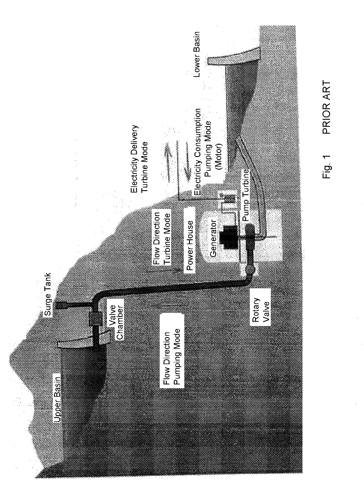
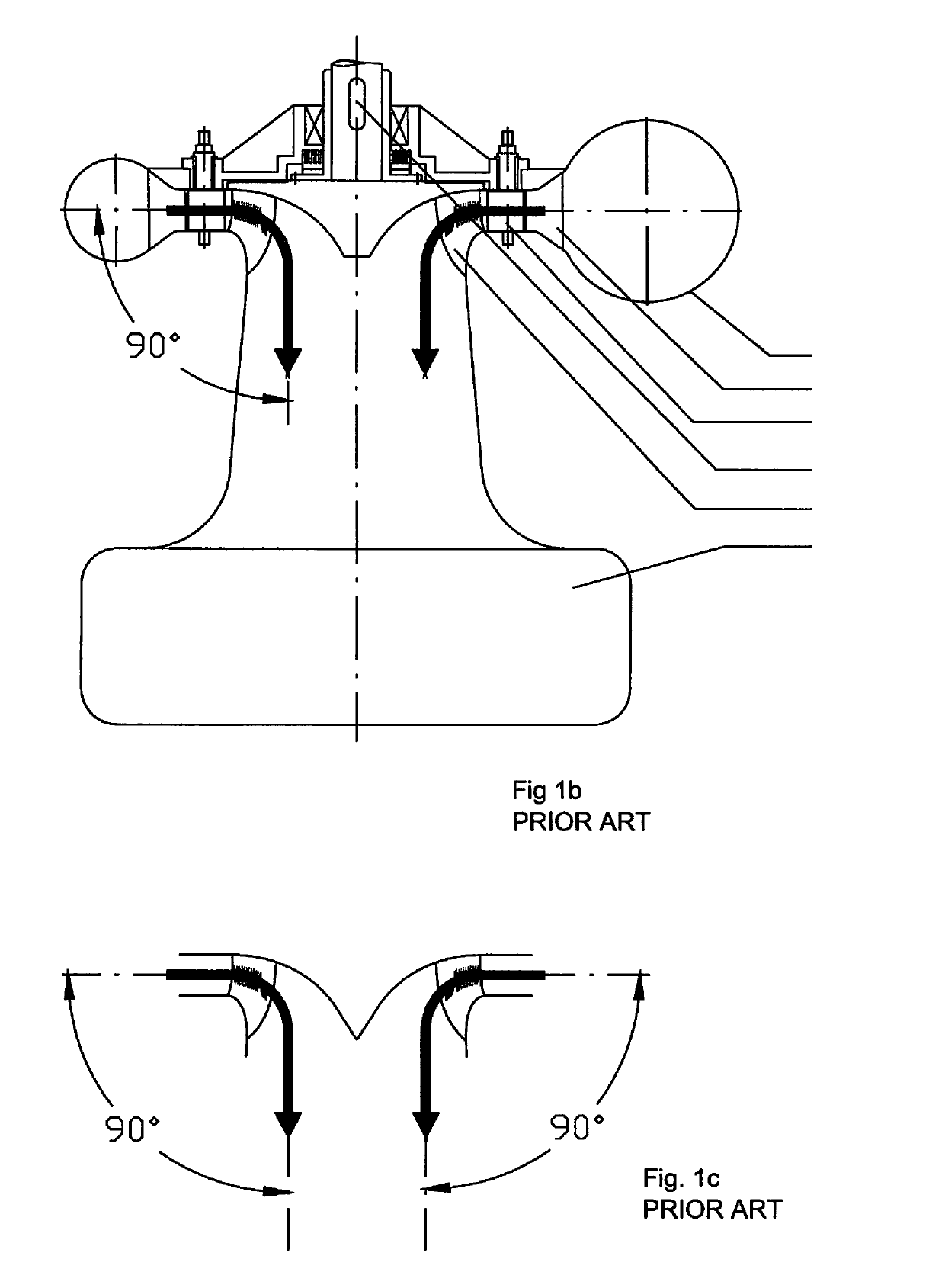
[0051]Referring to FIGS. 1a, 1b, and 1c, a conventional pumped storage plant with a reversible pump-turbine is shown. There are several notably expensive features in such a conventional installation. These include;[0052]1) A surge shaft that is typically needed to relieve waterhammer that can result from a load rejection.[0053]2) An underground powerhouse below tailwater level. Such a powerhouse is expensive to construct and is at risk of flooding due to human error or component failure. Flooding of an underground powerhouse is a hazard to the facility itself as well as to its operators.[0054]3) The penstock and tailrace conduit must be routed, at great expense to the same low elevation as the powerhouse itself.

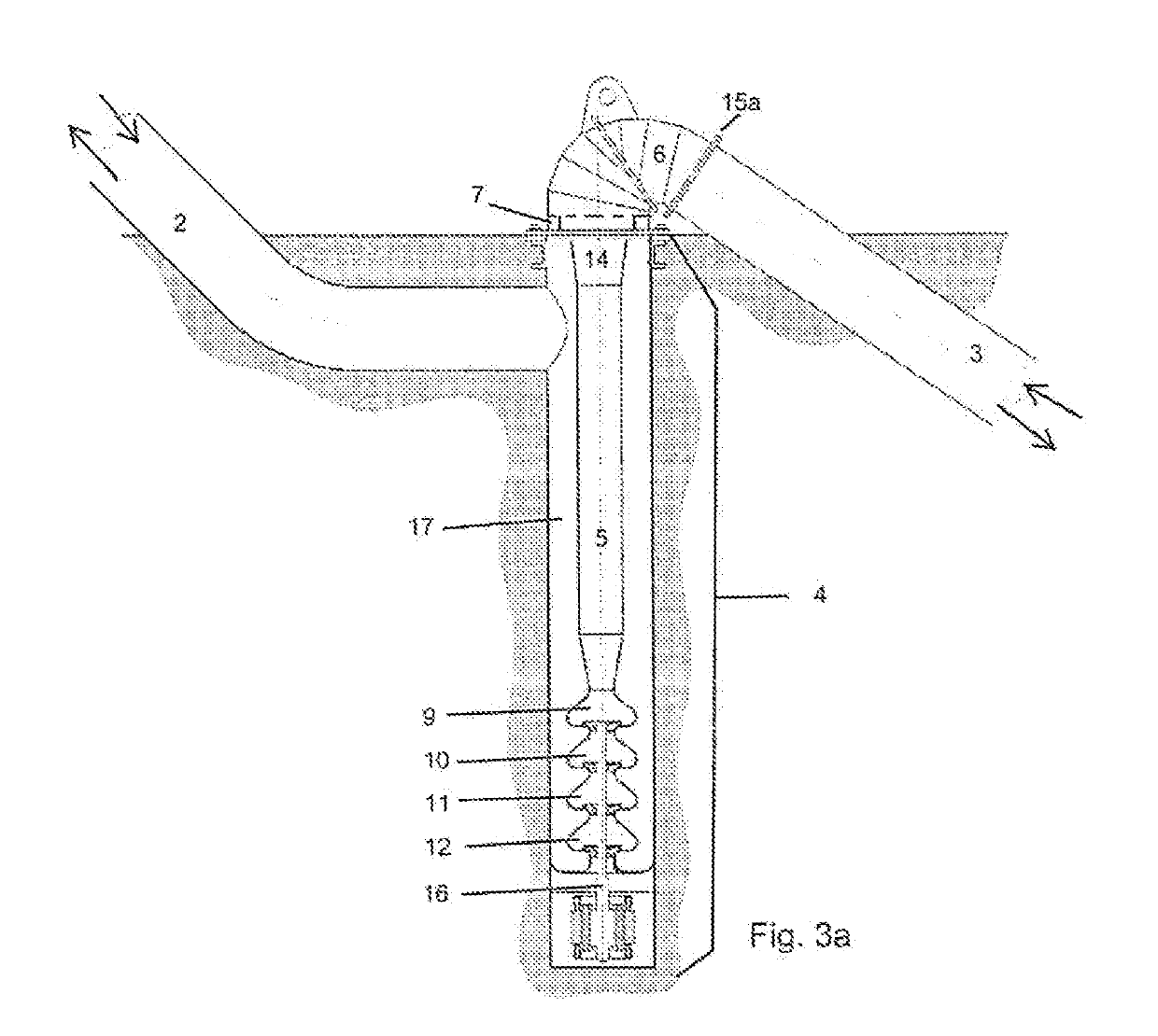
[0055]Referring to FIG. 3a and FIG. 3b, a reversible pump-turbine installation in accordance with the present invention is shown. No underground powerhouse is required. Instead, a vertical borehole or shaft 4 allows the pump-turbine and motor-generator assembly 1 to be instal...


PUM


Abstract

The present invention is a reversible pump-turbine installation position in a vertical shaft instead of in a conventional underground powerhouse or deep concrete powerhouse. The required plant cavitation coefficient may be achieved by simply boring a vertical shaft to the required depth rather than routing the water flow to and from a deeply buried powerhouse. A pneumatically controlled pressure relief valve may be incorporated into this invention.

Description

FIELD OF THE INVENTION[0001]The present invention relates to reversible pump-turbines used for storage of electrical energy. Conventional pumped storage facilities as shown in FIG. 1b generally use an underground powerhouse to provide sufficient absolute pressure at the runner to prevent destructive cavitation. The elevation of the runner may be 100 meters below tailwater, for example. Constructing and maintaining such an underground facility is expensive and the expense does not decrease in proportion to size in the case of smaller facilities. There are therefore very few pumped storage facilities of less than 100 MW in North America. A typical conventional pump-turbine sectional elevation is shown in FIG. 1b. The prior art pump-turbine flow path with a 90 degree turn in the meridional plane is illustrated in FIG. 1c, this being similar to the flow path in the meridional plane of a conventional Francis turbine. The present invention relates to single purpose turbines and pumps as w...

Claims


Application Information

Patent Timeline
IPC IPC(8): F03B13/06E02B9/00F03B13/10
CPCF03B13/06E02B9/00F03B13/10F05B2220/32F03B3/103E02B9/06F03B13/02Y02E10/20Y02E60/16F04D1/04F04D29/2238F04D29/2283F04D29/4293F04D29/448F04D29/506F04D29/548
Inventor OBERMEYER, HENRY K.IAVORNIC, CLAUDIU M.BAKER, GRANT QUINN
Owner BHE TURBOMACHINERY LLC
Why Eureka
Try Eureka