
Display panel and charge sharing control method thereof

a control method and display panel technology, applied in the direction of instruments, static indicating devices, etc., can solve the problems of relatively high corresponding power consumption, achieve the effects of enhancing the charge sharing effect, prolonging the charge sharing time, and improving the quality of the display screen

Active Publication Date: 2019-06-20
HKC CORP LTD +1
View PDF3 Cites 3 Cited by
  • Summary
  • Abstract
  • Description
  • Claims
  • Application Information

AI Technical Summary

Benefits of technology

The objective of this patent is to provide a display panel and a charge sharing control method that allows for direct charge sharing on pixel circuits, resulting in a prolonged charge sharing time and enhanced charge sharing effect. Additionally, without the need for an additional timing signal, charge sharing can be performed using dot inversion or column inversion to improve the quality of the display screen.

Problems solved by technology

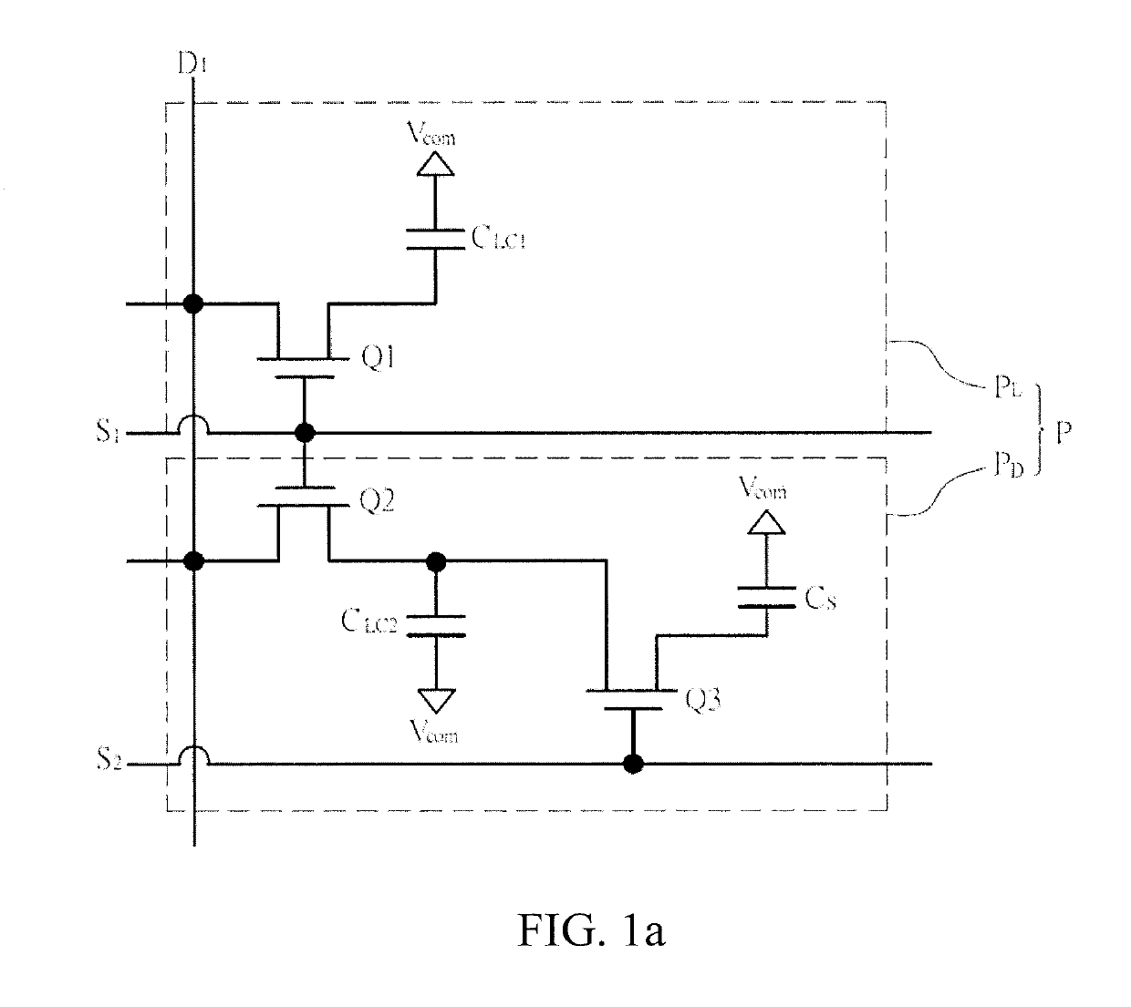
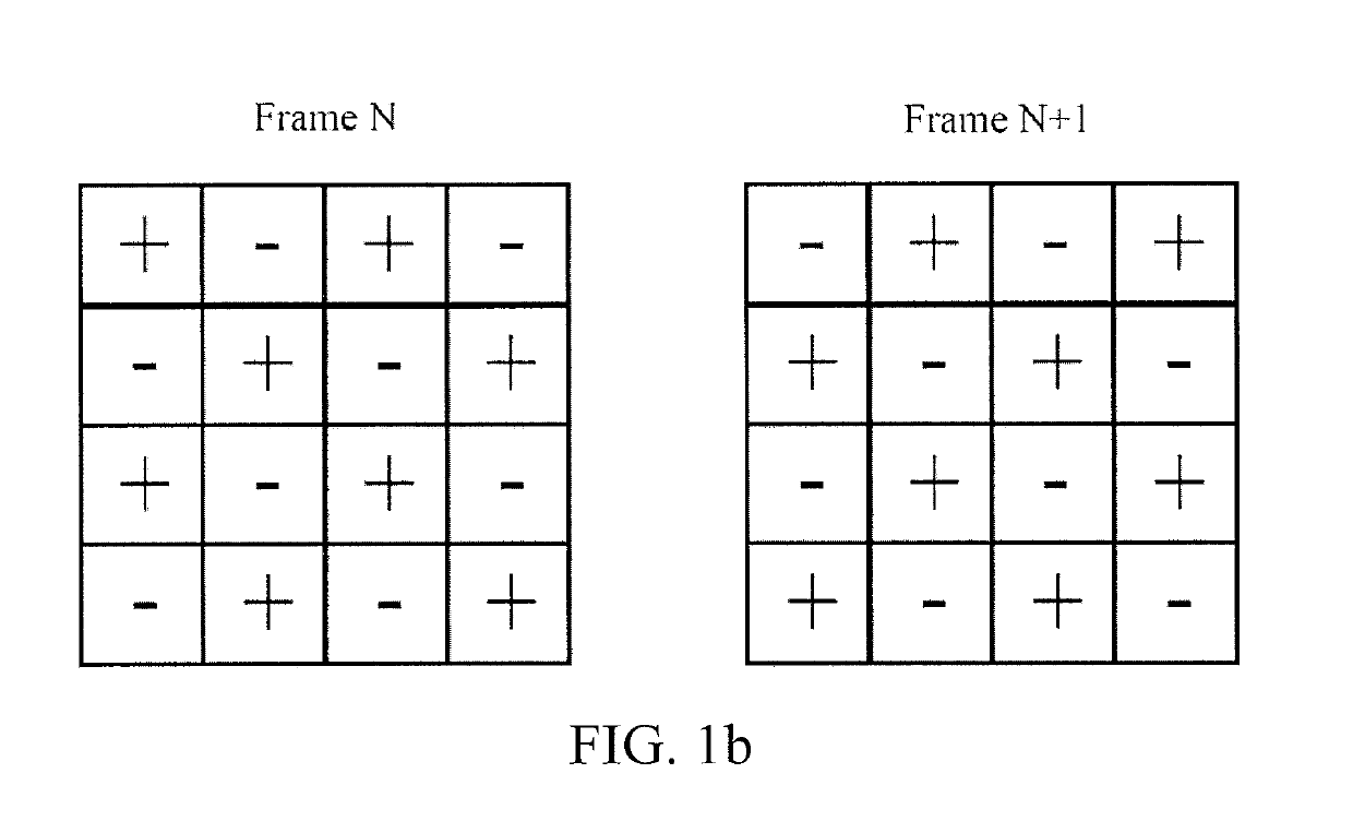
However, because a drive waveform used in a dot inversion is measured in an addressing time, and the dot inversion is a high-frequency inversion, corresponding power consumption is relatively high.

Method used


Image

  • Display panel and charge sharing control method thereof
  • Display panel and charge sharing control method thereof
  • Display panel and charge sharing control method thereof

Examples


Embodiment Construction

[0027]The following embodiments are described with reference to the accompanying drawings, used to exemplify specific embodiments for implementation of this application. Terms about directions mentioned in this application, such as “on”, “below”, “front”, “back”, “left”, “right”, “in”, “out”, and “side surface” merely refer to directions in the accompanying drawings. Therefore, the used terms about directions are used to describe and understand this application, and are not intended to limit this application.

[0028]The accompanying drawings and the description are considered to be essentially exemplary, rather than limitative. In the figures, units with similar structures are represented by using the same reference number. In addition, for understanding and ease of description, the size and the thickness of each component shown in the accompanying drawings are arbitrarily shown, but this application is not limited thereto.

[0029]In the accompanying drawings, for clarity, thicknesses o...


PUM


Abstract

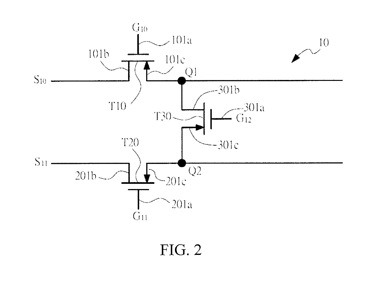
This application relates to a display panel. The display panel includes: a substrate, active switches are formed on the substrate; pixel units arranged in a matrix manner, where three of the pixel units form a pixel group, coupled to any data line and three scanning lines arranged in order, and the pixel group includes: a first pixel unit, coupled between a first scanning line and the data line; a second pixel unit, coupled between a second scanning line and the data line; and a third pixel unit, coupled between a third scanning line and the data line; and a charge sharing switch, where a control end of the charge sharing switch is connected to the first scanning line, a first end of the charge sharing switch is connected to the second pixel unit, and a second end of the charge sharing switch is connected to the third pixel unit.

Description

BACKGROUNDTechnical Field[0001]This application relates to a charge sharing method, and in particular, to a display panel and a charge sharing control method thereof.Related Art[0002]Liquid crystal displays (LCDs) have been widely applied in recent years. As drive technologies are improved, the LCDs have advantages such as low electric power consumption, a thin and light design, and low-voltage driving. Currently, the LCDs have been widely applied to camcorders, notebook computers, desktop displays, and various projection devices.[0003]However, an LCD panel usually includes a gate driver circuit, a source driver circuit, and a pixel array. The pixel array includes a plurality of pixel circuits, and each pixel circuit is switched on or off according to a scanning signal provided by the gate driver circuit. Moreover, a data screen is displayed according to a data signal provided by the source driver circuit.[0004]In a process of continuously reversing a polarity of a data line, power ...

Claims


Application Information

Patent Timeline
IPC IPC(8): G09G3/36
CPCG09G3/3614G09G3/3677G09G3/3688G09G2310/0251G09G3/3648G09G2300/0852G09G2330/021G09G2320/0247
Inventor ZHOU, MANCHENG
Owner HKC CORP LTD
Learn More