Superelastic bone compression staple

a superelastic bone and staple technology, applied in the field of room temperature superelastic bone compression staples, can solve the problems of limited mechanical interference, and achieve the effects of reducing the number of screws, and uniform cross-sectional shap

Active Publication Date: 2019-06-27
ORTHO SOLUTIONS HLDG LTD
View PDF9 Cites 9 Cited by
  • Summary
  • Abstract
  • Description
  • Claims
  • Application Information

AI Technical Summary

Benefits of technology

[0010]In addition, the staple has two, three, or four legs on either end of the bridge member. The legs may be joined to the bridge member by corner extensions which flow into the legs or may extend directly from the bridge for example from an inwardly curved recess in the ends of the bridge member. The legs preferably have a uniform cross-sectional shape which helps to eliminate stress risers, for example, at the conjunction of the legs and bridge. One optimal shape is a FIVE-sided polygon, such as pentagon. The staple is designed for optional removal, so that while the staple may include texturing, ridges, or barbs to improve the hold in bone, the amount of mechanical interference is limited, for example by the provision of low ridges and on one only one or two surfaces of the legs, such as on the inner surface facing inward on the leg. Thus, the staple design permits easy removal.

Problems solved by technology

The staple is designed for optional removal, so that while the staple may include texturing, ridges, or barbs to improve the hold in bone, the amount of mechanical interference is limited, for example by the provision of low ridges and on one only one or two surfaces of the legs, such as on the inner surface facing inward on the leg.

Method used


Image

  • Superelastic bone compression staple
  • Superelastic bone compression staple
  • Superelastic bone compression staple

Examples


Embodiment Construction

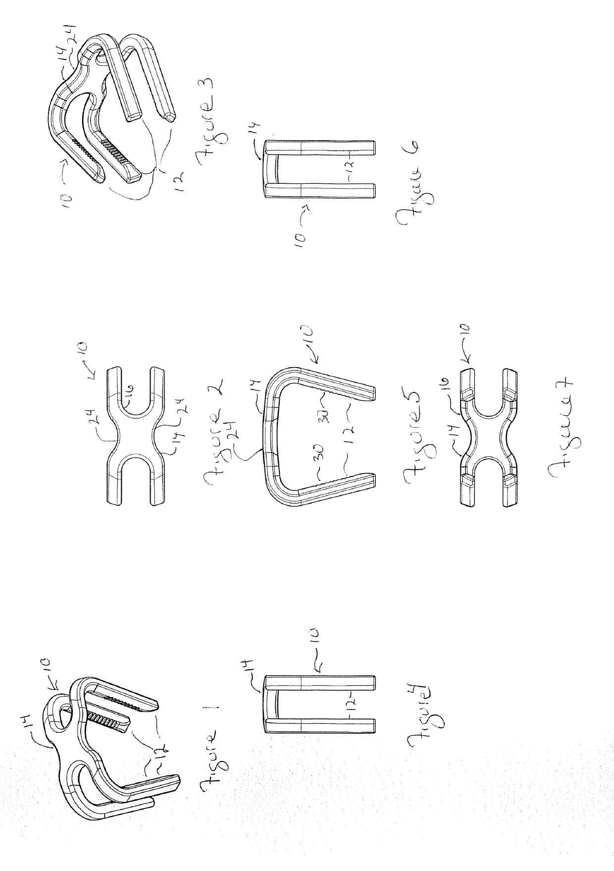
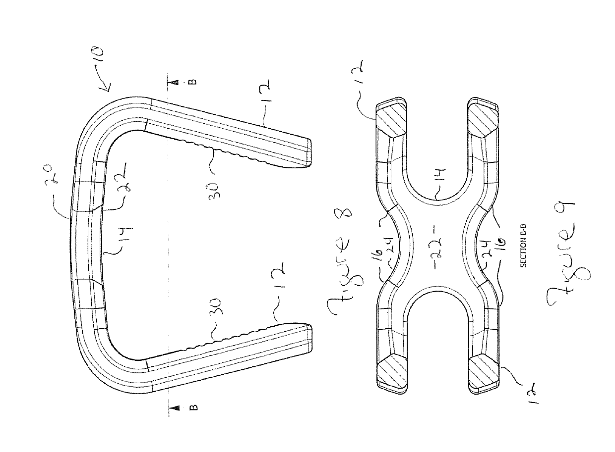
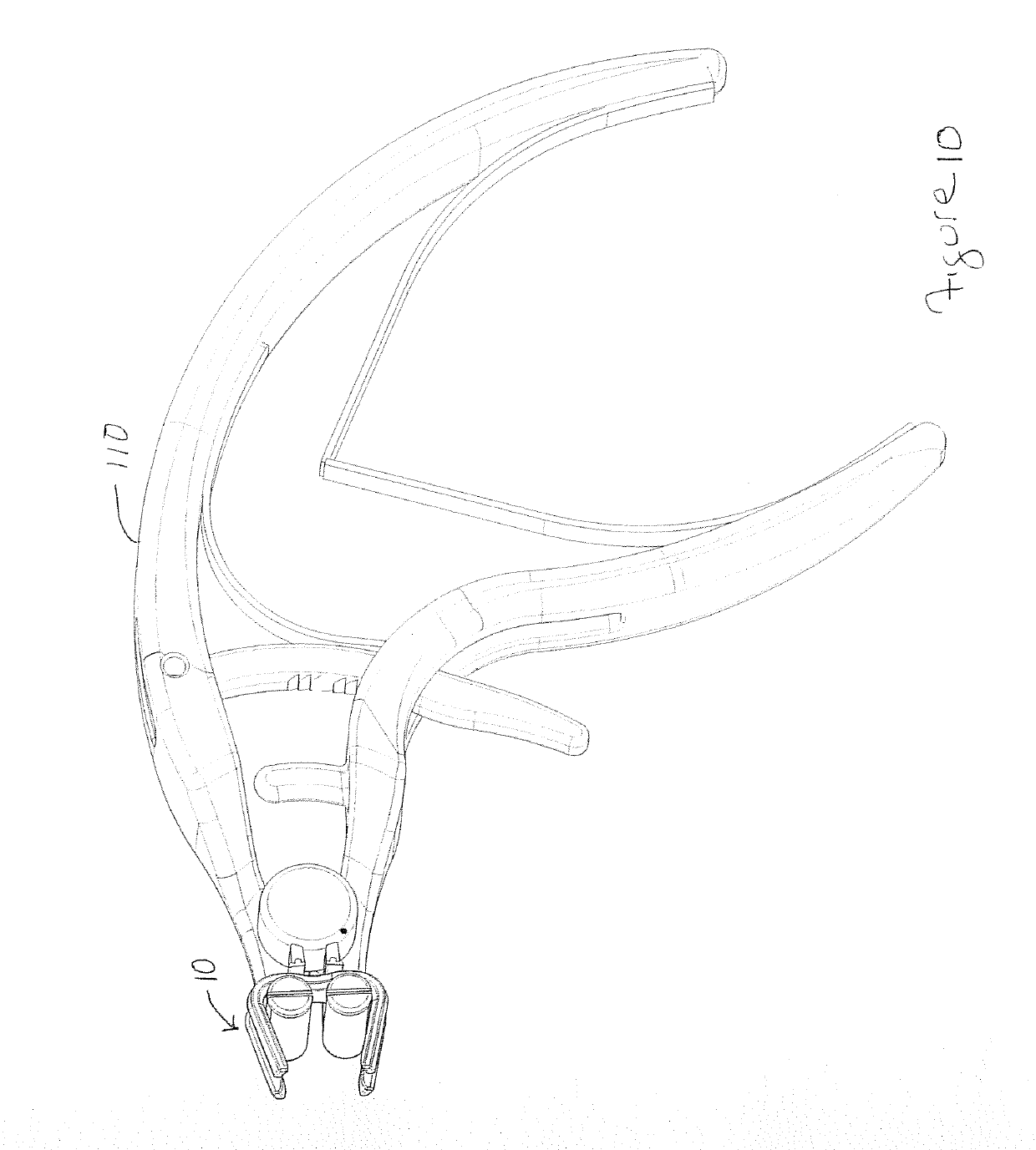
[0028]The present invention relates to a room temperature superelastic Nitinol bone compression staple 10. The staple 10 has two or more, and preferably 2, 3, or 4 legs 12 that will engage bones or bone segments through the cortical surfaces. The legs 12 are spaced apart from each other and joined together by bridge member 14 that extends across the area between legs at either end of the bridge member 14. As shown, the legs are joined to transitional extensions 16 which fold or curve at an angle of from 75° to 90°, and preferably from 85° to 90° relative to a long axis of the bridge member. On the other end, the extensions 16 join to the bridge member 14 and the bridge member has an inwardly curved recess between the legs at the ends of the axis (when there are two legs on an end), and as well between the legs on the same sides of the axis.

[0029]The bridge member 14 has a top surface 20 and a bottom surface 22 which have corresponding shapes so that they are separated by a constant ...


PUM


Abstract

The invention is a staple comprising a bridge member having a spherical top surface and a spherical opposing bottom surface defining a constant thickness between and having a constant thickness and a first pair of a first leg and a second leg and a second pair of a first leg and a second leg where the first and second pair of legs are spaced apart along the axis and are joined to the bridge member.

Description

FIELD OF THE INVENTION[0001]The present invention relates to a room temperature superelastic bone compression staple intended for bone fixation in the surgical management of fractures and reconstruction of the foot and hand. The staple is fabricated by machining a blank to form a staple in the closed (converging legs) shape and the resulting staple is mechanically deformed during use to induce the superelastic shape memory properties to compress bone segments and facilitate osteosynthesis. The staple has a bridge member preferably having a uniform thickness defined between an exterior and corresponding opposing interior surface each configured as a portion of a sphere. The bridge member joins two to four legs also having a unique configuration, such as a polygonal cross-section, and optional texturing or barbs on one or more surfaces to increase the anchoring of the legs in bone. The staple is provided having a range of different bridge widths ranging from 10 mm to 25 mm and various...

Claims


Application Information

Patent Timeline
Patent Type & Authority Applications(United States)
IPC IPC(8): A61B17/064
CPCA61B17/0642A61B2017/0641A61B17/0682A61B17/10A61B2017/00867A61B2017/0645A61B17/0644
Inventor DUCHARME, DUSTINMACLURE, ALISTERSTAMP, KEVIN
Owner ORTHO SOLUTIONS HLDG LTD
Why Eureka
Try Eureka