Tensioner

a technology of tensioner and tensioner body, which is applied in the direction of machine/engine, belt/chain/gearing, machine/engine, etc., can solve the problems of increasing flow resistance and inhibiting smooth pressure relief, so as to prevent the pressure from falling, facilitate assembly of the entire tensioner, and relieve the effect of pressur

Active Publication Date: 2019-06-27
TSUBAKIMOTO CHAIN CO
View PDF0 Cites 5 Cited by
  • Summary
  • Abstract
  • Description
  • Claims
  • Application Information

AI Technical Summary

Benefits of technology

[0030]According to the configuration set forth in claim 9, the outer surface protrusion of the cap member is formed in a shape that keeps the relief valve unit with a light press fit when the relief valve unit is inserted into the plunger hole. Since the relief valve unit is maintained inside the plunger hole, it is prevented from dropping during the assembling work of other components, so that the assembling of the entire tensioner is made easy.
[0031]According to the configuration set forth in claim 10, the cap member includes a holding recess that fits with the stopper member. Thus a lateral oil path is reliably provided on the stopper member for the released oil so that pressure is relieved smoothly during oil release with reduced flow resistance.
[0032]Also, the cap member and the stopper member can be fitted with each other when assembled, which makes the assembling of the relief valve unit easier.
[0033]According to the configuration set forth in claim 11, the cap member is integrally formed with the stopper member as a single member. The number of components is thus reduced, so that the assembling of the relief valve unit is made even easier.
[0034]According to the configuration set forth in claim 12, the cap member is made of a resin material, which allows for a higher degree of freedom in shape, enables a weight reduction, and further facilitates assembling of the relief valve unit. It also allows designing of an optimal oil path, and smooth pressure relief can be achieved during oil release with reduced flow resistance.
[0035]Moreover, the force applied to the plunger when the relief valve unit is pressed into the plunger hole is reduced so that plunger deformation is prevented and the plunger can be made thinner to be more lightweight, and can have a higher shape accuracy.

Problems solved by technology

This further increases the flow resistance and could inhibit smooth pressure relief during oil release.

Method used


Image

  • Tensioner
  • Tensioner
  • Tensioner

Examples


first embodiment

[0056]A tensioner according to the present invention will be described below with reference to the drawings.

[0057]First, the tensioner 110 is incorporated in a chain transmission used in a timing system or the like of a car engine. As shown in FIG. 20, the tensioner is attached to an engine block (not shown) to apply appropriate tension to the slack side of a drive chain CH passing over a plurality of sprockets S1 to S3 via a tensioner lever G to reduce vibration during the drive.

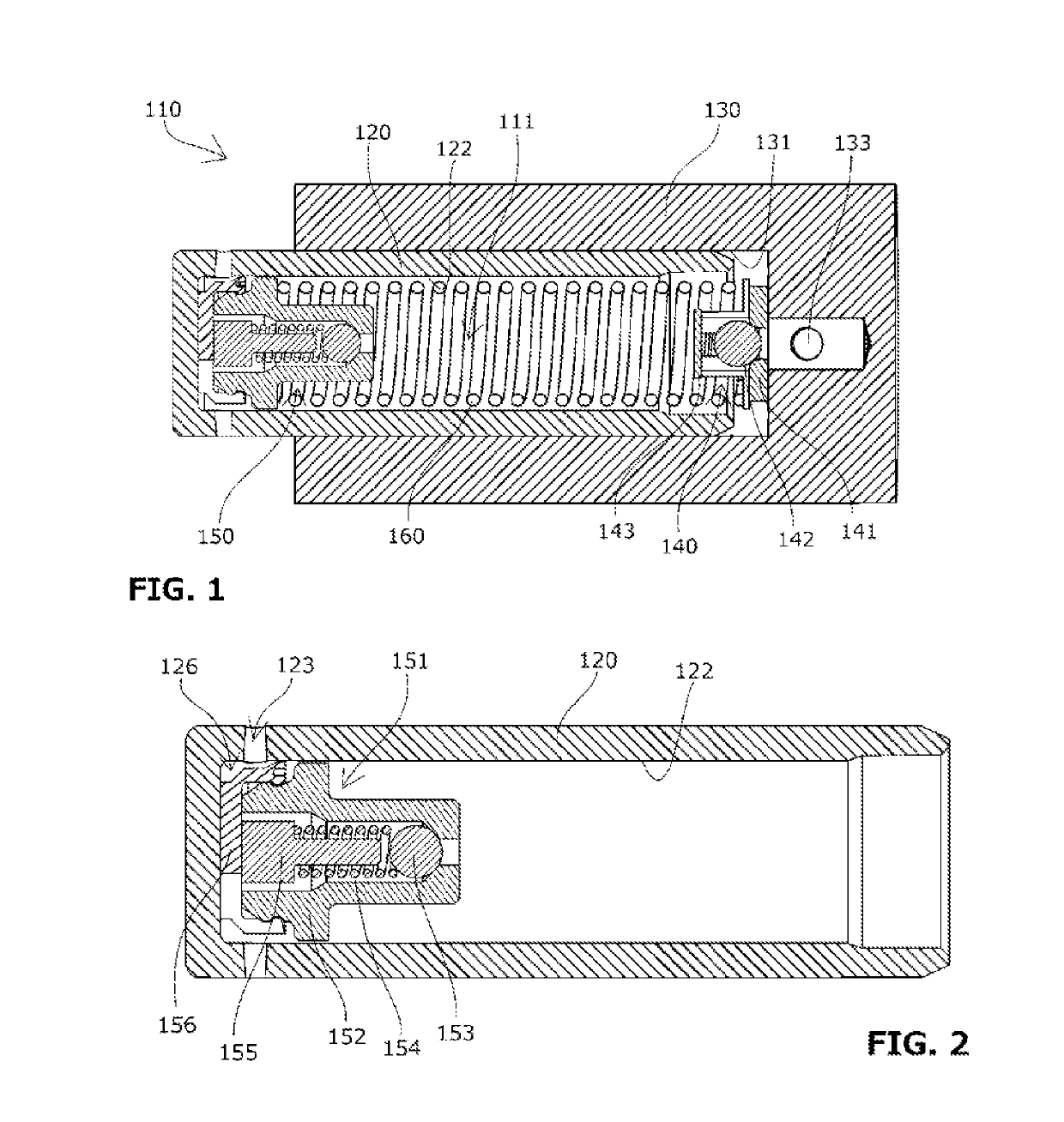
[0058]The tensioner 110 includes, as shown in FIG. 1, a plunger 120 having a plunger hole 122 that is open on a rear side, a housing 130 having a plunger bore 131 that is open on a front side for accommodating the plunger 120, a check valve 140 disposed on the bottom side of the housing 130, a relief valve mechanism 150 that releases oil from the oil pressure chamber 111 out of the plunger 120 when the oil pressure inside the oil pressure chamber 111 rises, and a main spring (main biasing means) 160 that is...

second embodiment

[0077]Next, a tensioner according to the present invention will be described with reference to the drawings.

[0078]Description of parts similar to those of the first embodiment will be omitted.

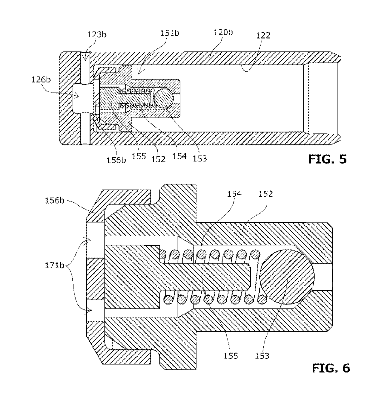
[0079]The plunger 120b of the tensioner according to the second embodiment includes a relief valve mechanism 150, as shown in FIG. 5, made up of a relief valve unit 151b inserted on the front side of the plunger hole 122, a relief-side space 126b formed as a recess at the bottom of the plunger hole 122, and an external relief hole 123b that causes the relief-side space 126b to communicate with the outside of the plunger 120b.

[0080]The external relief hole 123b opens radially in an outer circumferential surface of the plunger 120.

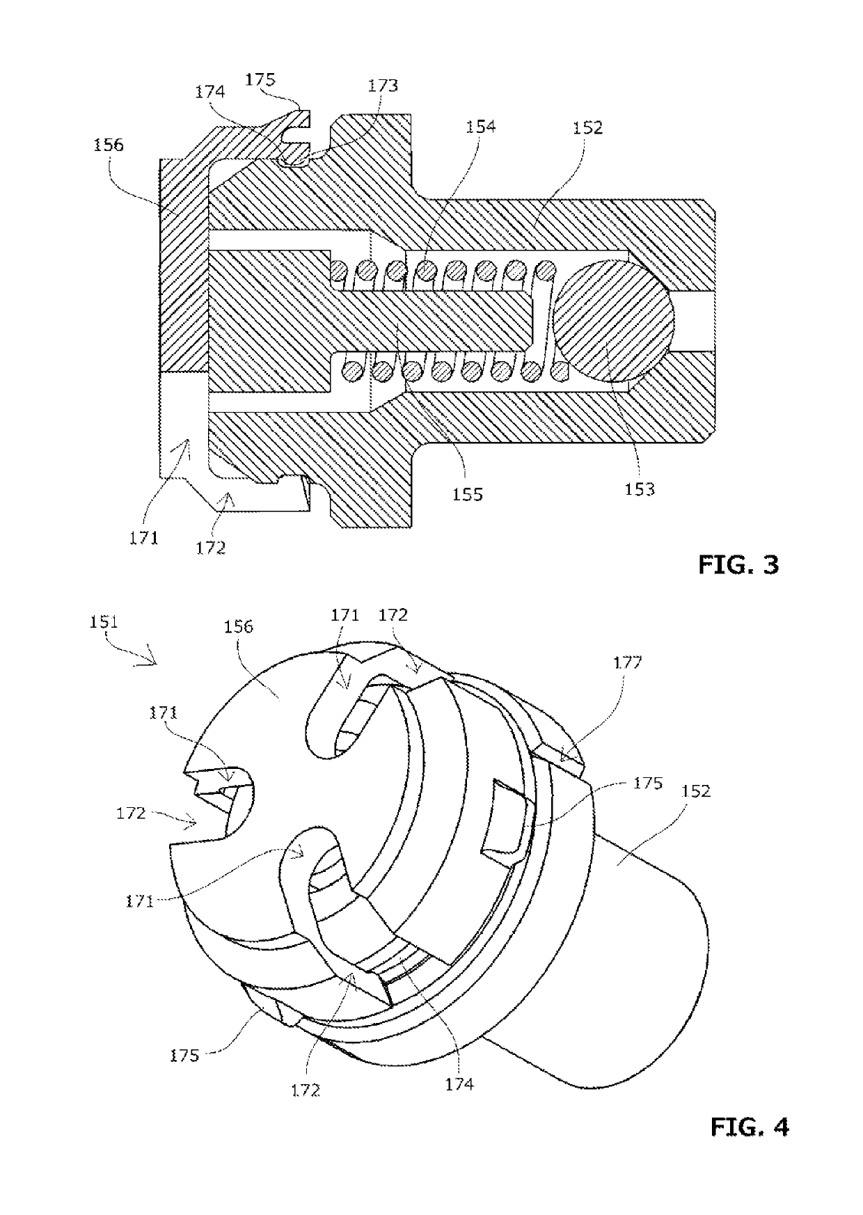
[0081]The relief valve unit 151b includes, as shown in FIG. 5 and FIG. 6, a seat member 152, a valve ball 153 housed in the seat member 152, a spring 154 biasing the valve ball 153, a stopper member 155 holding the spring 154 and restricting the movement range of the v...

third embodiment

[0100]The plunger 120g of the tensioner 110g includes a relief valve mechanism, as shown in FIG. 13, made up of a relief valve unit 151g inserted on the front side of the plunger hole 122g, and an external relief hole 123g that causes a relief-side space 126g of the relief valve unit 151g to communicate with the outside of the plunger 120g.

[0101]The external relief hole 123g opens radially in an outer circumferential surface of the plunger 120g.

[0102]The relief valve unit 151g includes, as shown in FIG. 13 to FIG. 15, a seat member 152g, a valve ball 153g housed in the seat member 152g, a spring 154g biasing the valve ball 153g, a stopper member 155g holding the spring 154g and restricting the movement range of the valve ball 153g, and a cap member 156g fitted with the seat member 152g to retain the stopper member 155g inside the seat member 152g.

[0103]The cap member 156g includes oil leak parts 171g for discharging released oil to the relief-side space 126g, as shown in FIG. 13...


PUM


Abstract

To provide a tensioner that has a simple structure and is easy to assemble, and is configured to smoothly relieve pressure during oil release with reduced flow resistance so that the oil pressure in an oil pressure chamber is kept stable in a favorable manner. A relief valve unit includes a cap member that fits with a seat member to retain a stopper member inside the seat member. An external relief hole, which causes a relief-side space in a plunger hole to communicate with the outside of a plunger, opens radially in an outer circumferential surface of the plunger.

Description

BACKGROUND OF THE INVENTION1. Field of the Invention[0001]The present invention relates to a tensioner that applies appropriate tension to a running chain, belt, or the like.2. Description of the Related Art[0002]It has been common practice to use a tensioner for maintaining appropriate tension of a chain or the like. For example, a chain guide mechanism has been known, which slidably guides, by means of a tensioner lever, a drive chain such as an endless roller chain passing over respective sprockets of a crankshaft and a cam shaft inside an engine room, and which uses a tensioner to bias the tensioner lever in order to maintain appropriate tension of the chain or the like.[0003]One known tensioner 510 used in such a chain guide mechanism includes, as shown in FIG. 18, a plunger 520 having a plunger hole 522 that is open on the rear side, a housing 530 having a plunger bore 531 that is open on the front side for accommodating the plunger 520, a relief valve mechanism 550 that relea...

Claims


Application Information

Patent Timeline
Patent Type & Authority Applications(United States)
IPC IPC(8): F02B67/06F16H7/08
CPCF02B67/06F16H7/0829F16H2007/0806F16H2007/0812F16H2007/0863F16H7/08F16H2007/0814
Inventor IWASAKI, YOSHITAKAWATANABE, MASANORIYOSHIDA, OSAMUKUREMATSU, YUJI
Owner TSUBAKIMOTO CHAIN CO
Why Eureka
Try Eureka