Pultruded fibrous composite strips having non-planar profiles cross-section for wind turbine blade spar caps

Active Publication Date: 2019-06-27
SIEMENS GAMESA RENEWABLE ENERGY AS
View PDF4 Cites 15 Cited by
  • Summary
  • Abstract
  • Description
  • Claims
  • Application Information

AI Technical Summary

Benefits of technology

[0017]In another embodiment of the strip, the first side further includes two peripheral surface regions—each extending longitudinally. The first abutment surface is limited between the peripheral surface regions of the first side and separated from the first and second longitudinal edges by the peripheral surface regions of the first side. Similarly, the second side further includes two peripheral surface regions—each extending longitudinally. The second abutment surface is limited between the peripheral surface regions of the second side and separated from the first and second longitudinal edges by the peripheral surface regions of the second side. In this embodiment, at least one of the peripheral surface regions is chamfered, i.e. includes a chamfer recess. In another embodiment of the stri

Problems solved by technology

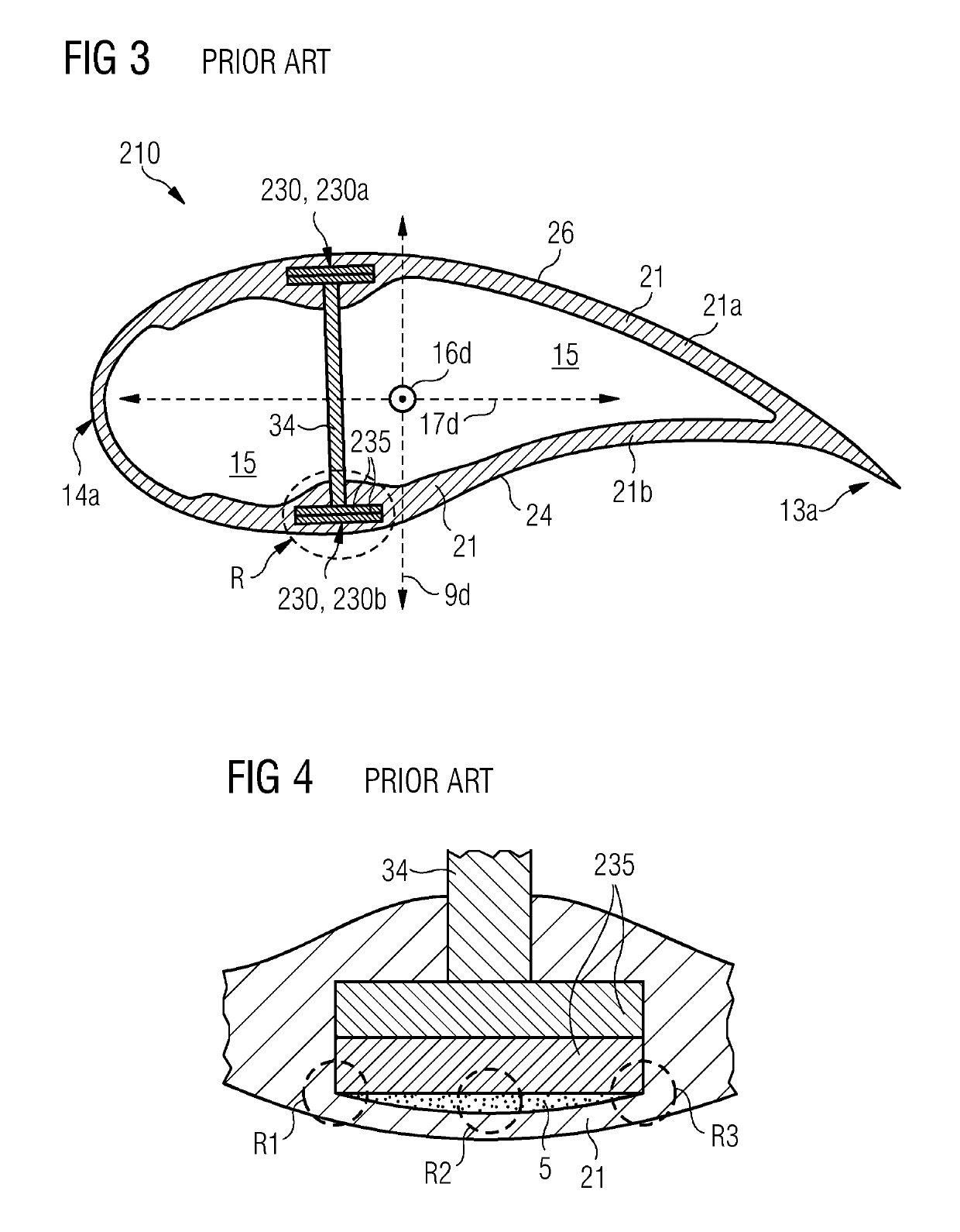
Larger sections, longer spans, thicker structural components of the blades make the resin flow very complex to design and optimize, and thus posing an increased risk of manufacturing errors such as transverse wrinkles, poor impregnation of the resin, air pockets, large areas with dry fibers, and so on and so forth.
These errors can extend over wide areas, can be very time consuming and very costly to repair and can drastically affect the cost and reliability of the final product i.e. the manufactured blade fo

Method used


Image

  • Pultruded fibrous composite strips having non-planar profiles cross-section for wind turbine blade spar caps
  • Pultruded fibrous composite strips having non-planar profiles cross-section for wind turbine blade spar caps
  • Pultruded fibrous composite strips having non-planar profiles cross-section for wind turbine blade spar caps

Examples


Embodiment Construction

[0038]Hereinafter, above-mentioned and other features of the present technique are described in detail. Various embodiments are described with reference to the drawing, wherein like reference numerals are used to refer to like elements throughout. In the following description, for the purpose of explanation, numerous specific details are set forth in order to provide a thorough understanding of one or more embodiments. It may be noted that the illustrated embodiments are intended to explain, and not to limit embodiments of the invention. It may be evident that such embodiments may be practiced without these specific details.

[0039]It may be noted that in the present disclosure, the terms “first”, “second”, “third” etc. are used herein only to facilitate discussion and carry no particular temporal or chronological significance unless otherwise indicated.

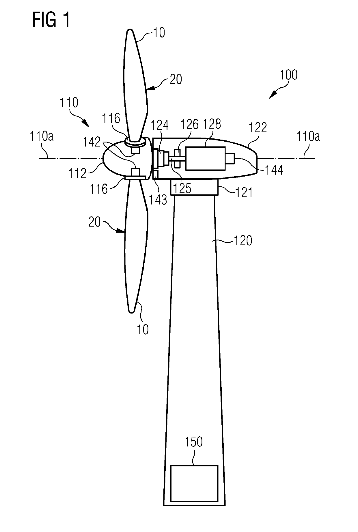
[0040]FIG. 1 shows an exemplary embodiment of a wind turbine 100 of the present technique. The wind turbine 100 includes a tower 120,...


PUM


Abstract

A pultruded fibrous composite strip, a spar cap made from such strips, a wind turbine rotor blade having such a spar cap and a method for making a spar cap from such strips is provided. The strip is stacked with similar strips to form the spar cap. The strip has a substantially constant cross-section defined by first and second mutually opposed and longitudinally extending sides, and by first and second longitudinal edges. The first and the second sides include first and second abutment surfaces, respectively. The first and the second abutment surfaces are non-planar. When the strip is stacked with similar strips, and subsequently integrated within shell of the wind turbine blade, the non-planar profile of the strips at least partially obviates formation of resin rich pockets at the interface of the spar cap and the shell and/or stress concentration between the edges of the spar cap and the shell.

Description

CROSS-REFERENCE TO RELATED APPLICATIONS[0001]This application claims priority to European application No. EP 17210022.4 having a filing date of Dec. 22, 2017 the entire contents of which are hereby incorporated by reference.FIELD OF TECHNOLOGY[0002]The following relates generally to wind turbines, and in particular, to a spar cap of a wind turbine rotor blade. More specifically, the following relates to pultruded unidirectional fibrous composite strips, spar caps having a stack of such pultruded unidirectional fibrous composite strips, and a method for making a spar cap with such pultruded unidirectional fibrous composite strips.BACKGROUND[0003]Dimensions of wind turbines and wind blades are ever increasing, and consequently are increasing the challenges to overcome during the manufacturing processes of such wind turbine rotor blades. Presently, preferred materials used to manufacture wind turbine rotor blades, hereinafter also referred to as the blades, are glass- and / or carbon-fib...

Claims


Application Information

Patent Timeline
IPC IPC(8): F03D1/06B29C70/52
CPCF03D1/0675B29C70/52F05B2230/20F05B2240/301B29L2031/085F03D1/0633F03D80/00B29C70/48B29D99/0028
Inventor GIROLAMO, DONATOOSTERGAARD KRISTENSEN, JENS JORGENNOERLEM, MICHAEL
Owner SIEMENS GAMESA RENEWABLE ENERGY AS
Why Eureka
Try Eureka