

Inspection Of A Shoe With A Thermal Camera
- Summary
- Abstract
- Description
- Claims
- Application Information
AI Technical Summary
Benefits of technology
Problems solved by technology
Method used
Image

Examples
Embodiment Construction
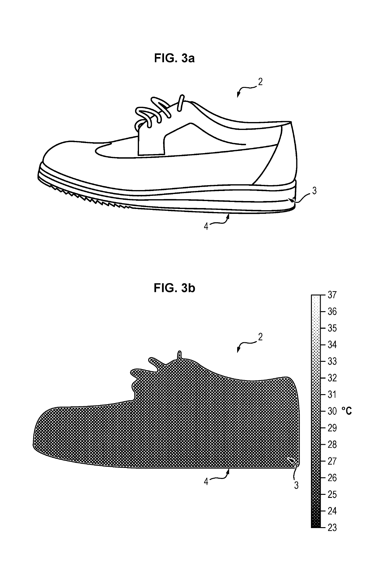
[0070]To detect target objects, the invention proposes using one or more thermal cameras 7 for determining a distance 6 (along an axis normal to the floor) between a floor and the lower face of the heel of the wearer and using this information for detecting the possible presence of a target object in the shoe 2. This distance 6 corresponds to the thickness of the sole 3, when the individual is not transporting a target object between the foot and the sole 3.
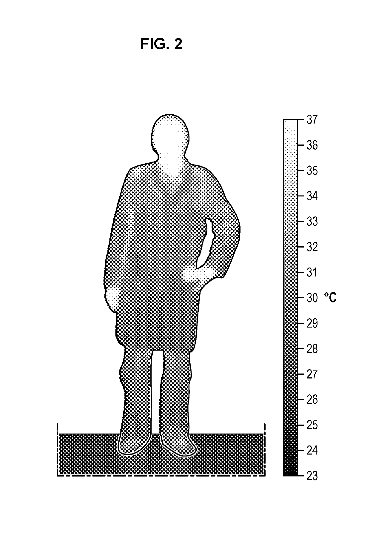
[0071]Thermal camera 7 (also known as infrared camera) here means a device configured to record infrared radiations emitted by a body and which vary as a function of their temperature.
[0072]Thermal cameras 7 have already been used for inspection of individuals. Yet to the extent where a thermal camera 7 does not obtain a precise image of the contours of the body of an individual when the latter is clothed, they are currently employed only in detecting when a line is crossed (infrared barriers) or for determining a distance betwee...
PUM
 Abstract
Description
Claims
Application Information