
Battery module and manufacturing method thereof

a battery module and manufacturing method technology, applied in the field of batteries, can solve the problems of complex process of manufacturing batteries, increase time and cost, and cannot solve the above-described problems, and achieve the effect of reducing manufacturing time and cost, increasing workability, and increasing workability

Pending Publication Date: 2019-06-27
SK ON CO LTD
View PDF10 Cites 56 Cited by
  • Summary
  • Abstract
  • Description
  • Claims
  • Application Information

AI Technical Summary

Benefits of technology

The present invention provides a battery module and a manufacturing method that can maximize space utilization and energy density, while reinforcing strength and rigidity for improved assembly. Additionally, the invention facilitates easy application of a fixing / heat transfer resin and insertion of a battery group during manufacturing.

Problems solved by technology

Furthermore, since respective sides of the battery module case are separately prepared as a separate component, and then are coupled with each other, a process of manufacturing the battery module is complicated, as well as time and costs are increased.
For example, Korean Patent Registration No. 10-1560217 discloses a battery module with improved cooling efficiency, which includes cooling members mounted on at least one surface of a stack of battery cells, and an electric insulation thermal conductive member provided between the stack of battery cells and the cooling member, however, it did not solve the above-described problems.

Method used


Image

  • Battery module and manufacturing method thereof
  • Battery module and manufacturing method thereof
  • Battery module and manufacturing method thereof

Examples


Embodiment Construction

[0076]Hereinafter, specific embodiments of the present invention will be described with reference to the accompanying drawings. However, these are merely illustrative examples and the present invention is not limited thereto.

[0077]In descriptions of the embodiments of the present invention, publicly known techniques that are judged to be able to make the purport of the present invention unnecessarily obscure will not be described in detail. Referring to the drawings, wherein like reference characters designate like or corresponding parts throughout the several views. In addition, the terms as used herein are defined by taking functions of the present disclosure into account and can be changed according to the custom or intention of users or operators. Therefore, definition of the terms should be made according to the overall disclosure set forth herein.

[0078]It should be understood that the technical spirit and scope of the present invention are defined by the appended claims, and t...


PUM

PropertyMeasurementUnit
operating voltageaaaaaaaaaa
currentaaaaaaaaaa
temperatureaaaaaaaaaa

Abstract

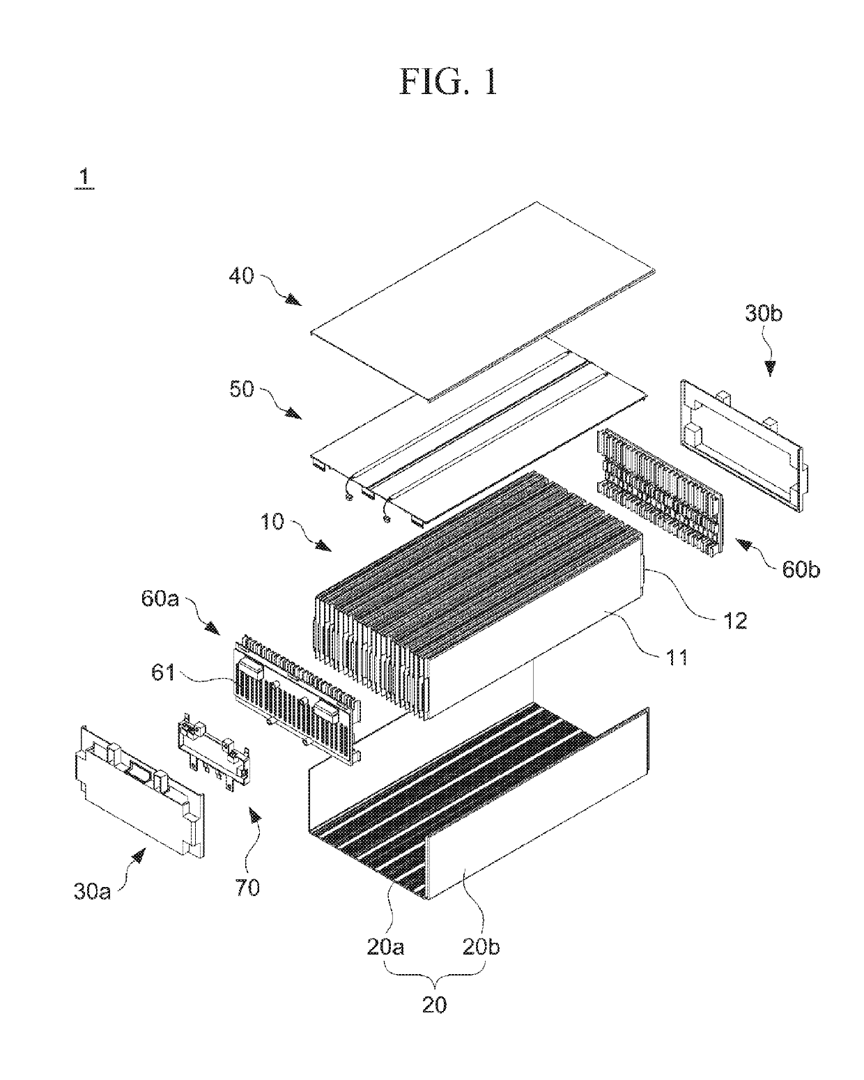
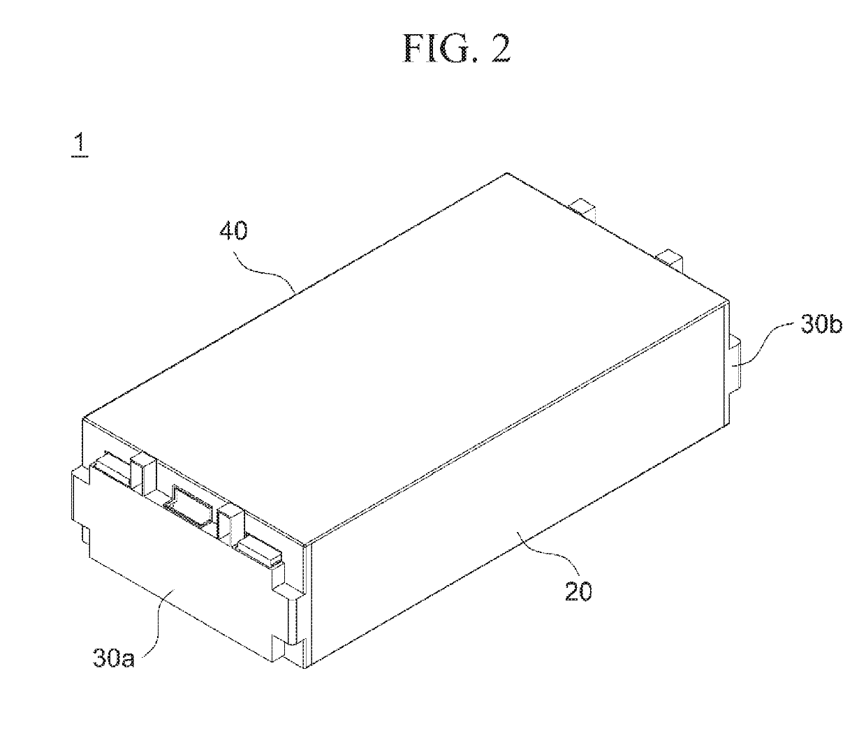
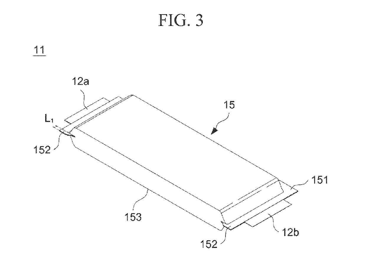
The present invention provides a battery module, which includes: a battery group formed by stacking a plurality of battery cells, each of which includes electrode tabs; a cooling housing including a cooling plate located corresponding to one side of sides of the battery group, in which the electrode tabs are not extended, and side plates located on both sides of the battery group perpendicular to the one side of the sides, thus to house the battery group; a cover plate located on the other side of the battery group; and a front cover part and a rear cover part, which are located at outermost front and rear of the battery group on both sides in a direction in which the electrode tabs are extended.

Description

BACKGROUND OF THE INVENTION1. Field of the Invention[0001]Embodiments of the present invention relate to a battery module and a manufacturing method thereof.2. Description of the Related Art[0002]Research into a rechargeable secondary battery capable of being charged and discharged has been actively conducted in accordance with the development of state-of-the-art fields such as a digital camera, a cellular phone, a laptop computer, a hybrid automobile and the like. An example of the secondary battery includes a nickel-cadmium battery, a nickel-metal hydride battery, a nickel-hydrogen battery, and a lithium secondary battery. Among them, the lithium secondary battery, which has operating voltage of 3.6 V or more, is used as a power supply of a portable electronic device, or is used for a high output hybrid automobile by connecting a plurality of lithium secondary batteries are connected in series with each other to thereby be used for a high output hybrid automobile. Since the lithiu...

Claims


Application Information

Patent Timeline
Patent Type & Authority Applications(United States)
IPC IPC(8): H01M10/6554H01M10/613H01M2/10H01M2/26H01M2/20H01M50/211H01M50/271H01M50/291H01M50/507H01M50/569
CPCH01M10/6554H01M10/613H01M2/1061H01M2/26H01M2/204H01M2/1077H01M2/206H01M10/655H01M10/6551H01M10/637H01M50/291H01M50/271H01M50/211H01M50/569H01M50/507Y02E60/10H01M10/48H01M50/20H01M50/502H01M10/482H01M10/653H01M10/647H01M50/258H01M50/54H01M50/209H01M50/186
Inventor CHOI, YANG KYUSON, SOL SANLIM, DONG HUNJU, SEUNG HOON
Owner SK ON CO LTD
Learn More