
Structure of mac sub-header for supporting next generation mobile communication system and method and apparatus using the same

a mobile communication system and structure technology, applied in network traffic/resource management, network topologies, wireless network protocols, etc., can solve the problems of increasing the size of each component does not exactly reflect the real size, and the processing burden of the terminal may be increased, so as to increase the data processing efficiency and reduce the processing burden. , the effect of low latency

Active Publication Date: 2019-06-27
SAMSUNG ELECTRONICS CO LTD
View PDF0 Cites 5 Cited by
  • Summary
  • Abstract
  • Description
  • Claims
  • Application Information

AI Technical Summary

Benefits of technology

The present patent proposes a method for reducing power consumption of a terminal in a mobile communication system. It also suggests conditions and procedures for selecting resource pools of terminals supporting communication between a vehicle and a pedestrian terminal to efficiently manage power consumption and increase the success rate of transmitting data with high priority.

Problems solved by technology

Further, the size of each component does not exactly reflect its real size.
Therefore, the processing burden of the terminal may be increased.
For example, if many types of MAC CEs need to be defined, they all may be difficult to be mapped to LCIDs.
As described above, in order for the terminal to acquire the scheduling information, continuously monitoring the PDCCH will cause large power consumption.
However, in the INACTIVE state, the flexible setting from the base station 4f-03 is restrictive differently from the RRC connected state, and therefore there is a need to introduce the restrictive method.
Performing the above operation every time all the downlink packets are received not only causes considerable processing consumption but also is unnecessary.
On the other hand, if the terminal has only one radio, the connection with the source system will be restricted.
However, the service quality, such as the delay time and the transmission rate may be somewhat lowered.
If the specific process (attach process to the target LTE system) is not completed until the timer expires, the dual-registered process is considered to have failed.
The failure report may include the frequency information or cell ID information that failed to the access and a cause of the failure.
The possible causes of the failure may include system information acquisition failure, random access failure, the expiration of the specific timer, or the like.
If the specific process (attach process to the target next generation mobile communication system) is not completed until the timer expires, the dual-registered process is considered to have failed.
The failure report may include the frequency information or cell ID information that failed to the access and a cause of the failure.
The possible causes of the failure may include system information acquisition failure, random access failure, the expiration of the specific timer, or the like.
This means the long service disconnection for the terminal that does not support dual radio.
However, the target system may already be in a network congestion state by servicing many terminals.
Therefore, if the dual registration is performed on such a target system, the above object will not be achieved.
Referring to FIG. 6G, the terminal that performs the dual-registered may experience a phenomenon of transmit power shortage in the uplink.
In the case of the terminal having the dual radio, data can be transmitted and received between two cells at the same time during the dual-registered operation, and if the data transmission timings overlap in the uplink, the transmit power may be insufficient on the terminal side.
The remaining links may be transmitted with the remaining small amount of transmit power, or may restrict the transmission itself.

Method used


Image

  • Structure of mac sub-header for supporting next generation mobile communication system and method and apparatus using the same
  • Structure of mac sub-header for supporting next generation mobile communication system and method and apparatus using the same
  • Structure of mac sub-header for supporting next generation mobile communication system and method and apparatus using the same

Examples


first embodiment

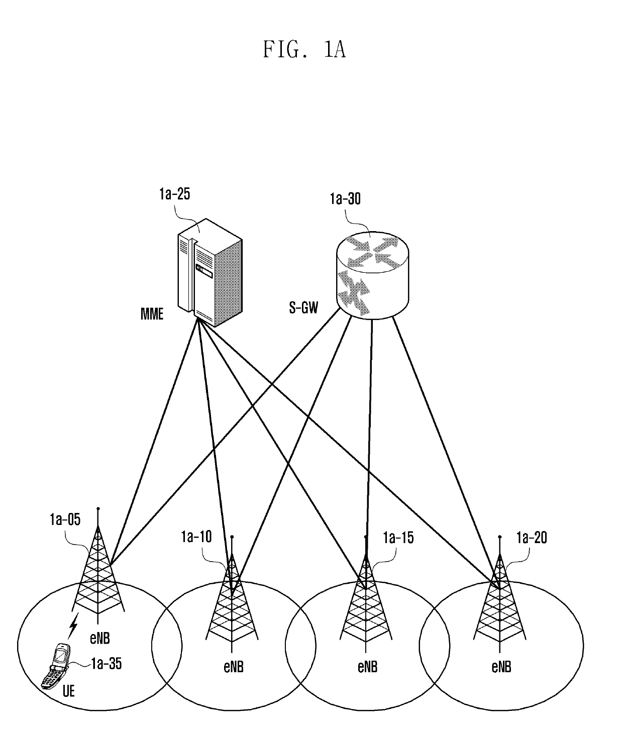
[0152]FIG. 1A is a diagram illustrating a structure of a long term evolution (LTE) system according to an embodiment of the present disclosure.

[0153]Referring to FIG. 1A, a radio access network of an LTE system is configured to include next generation base stations (evolved node B, hereinafter, eNB, Node B, or base station) 1a-05, 1a-10, 1a-15, and 1a-20, a mobility management entity (MME) 1a-25, and a serving-gateway (S-GW) 1a-30. User equipment (hereinafter, UE or terminal) 1a-35 accesses an external network through the eNBs 1a-05 to 1a-20 and the S-GW 1a-30.

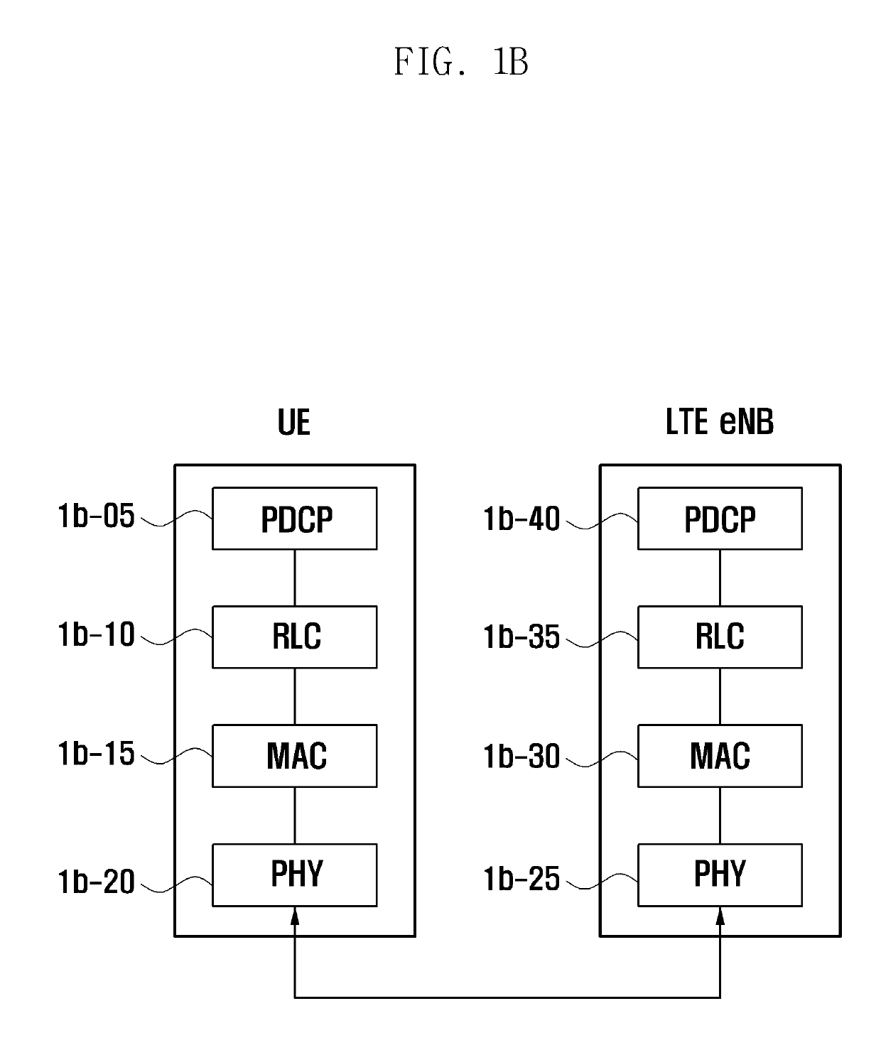
[0154]A user equipment (hereinafter, UE or terminal) 1a-35 accesses an external network through the eNBs 1a-05 to 1a-20 and the S-GW 1a-30. The eNB is connected to the UE 1a-35 through a radio channel and performs more complicated role than the existing node B. In the LTE system, in addition to a real-time service like a voice over Internet protocol (VoIP) through the Internet protocol, all the user traffics are served through...

second embodiment

[0297]FIG. 2A is a diagram illustrating a structure of an LTE system according to an embodiment of the present disclosure.

[0298]Referring to FIG. 2A, a radio access network of an LTE system is configured to include next generation base stations (evolved node B, hereinafter, eNB, Node B, or base station) 2a-05, 2a-10, 2a-15, and 2a-20, a mobility management entity (MME) 2a-25, and a serving-gateway (S-GW) 2a-30. User equipment (hereinafter, UE or terminal) 2a-35 accesses an external network through the eNBs 2a-05 to 2a-20 and the S-GW 2a-30.

[0299]Referring to FIG. 2A, the eNB 2a-05 to 2a-20 correspond to the existing node B of the UMTS system. In the LTE system, in addition to a real-time service like a voice over Internet protocol (VoIP) through the Internet protocol, all the user traffics are served through a shared channel and therefore an apparatus for collecting and scheduling status information, such as a buffer status, an available transmit power status, and a channel state of...

third embodiment

[0435]FIG. 3A is a diagram illustrating a structure of an LTE system according to an embodiment of the present disclosure.

[0436]Referring to FIG. 3A, a radio access network of an LTE system is configured to include next generation base stations (evolved node B, hereinafter, eNB, Node B, or base station) 3a-05, 3a-10, 3a-15, and 3a-20, a mobility management entity (MME) 3a-25, and a serving-gateway (S-GW) 3a-30. User equipment (hereinafter, UE or terminal) 3a-35 accesses an external network through the eNBs 3a-05 to 3a-20 and the S-GW 3a-30.

[0437]In FIG. 3A, the eNB 3a-05 to 3a-20 correspond to the existing node B of the UMTS system. The eNB is connected to the UE 3a-35 through a radio channel and performs more complicated role than the existing node B. In the LTE system, in addition to a real-time service like a voice over Internet protocol (VoIP) through the Internet protocol, all the user traffics are served through a shared channel and therefore an apparatus for collecting and sc...


PUM


Abstract

A communication technique of fusing a fifth generation (5G) communication system for supporting higher data transmission rate beyond a fourth generation (4G) system with an Internet of things (IoT) technology and a system thereof are provided. The communication technique may be used for an intelligent service (for example, a smart home, a smart building, a smart city, a smart car or a connected car, health care, digital education, a retail business, a security and safety related service, or the like) based on the 5G communication technology and the IoT related technology. A method for defining media access control (MAC) sub-header structures suitable for a next generation mobile communication system and applying the MAC sub-header structures to provide a high data transmission rate and a low latency in the next generation mobile communication system is provided.

Description

CROSS-REFERENCE TO RELATED APPLICATION(S)[0001]This application is a continuation application of prior application Ser. No. 15 / 802,051, filed on Nov. 2, 2017, and was based on and claimed priority under 35 U.S.C. § 119(a) of a Korean patent application number 10-2016-0146353, filed on Nov. 4, 2016, in the Korean Intellectual Property Office, of a Korean patent application number 10-2016-0150848, filed on Nov. 14, 2016, in the Korean Intellectual Property Office, of a Korean patent application number 10-2016-0179455, filed on Dec. 26, 2016, in the Korean Intellectual Property Office, and of a Korean patent application number 10-2017-0026682, filed on Feb. 28, 2017, in the Korean Intellectual Property Office, the disclosure of each of which is incorporated by reference herein in its entirety.TECHNICAL FIELD[0002]The present disclosure relates to an operation of a terminal and a base station in a next generation mobile communication system. More specifically, the present disclosure rel...

Claims


Application Information

Patent Timeline
IPC IPC(8): H04W28/06H04W80/02H04W72/04
CPCH04W28/065H04W80/02H04W72/0406H04W84/042H04W88/08H04W88/02H04W28/06H04B7/2612H04B7/15542H04W72/04H04W72/20
Inventor KIM, DONGGUNKIM, SOENGHUNJIN, SEUNGRIKIM, SANGBUMVAN LIESHOUT, GERT-JANSAYENKO, ALEXANDERJANG, JAEHYUK
Owner SAMSUNG ELECTRONICS CO LTD
Learn More