Autonomous Mobile Platform with Harvesting System and Pest and Weed Suppression Systems

Active Publication Date: 2019-07-04
DCENTIZED SYST LLC
View PDF0 Cites 26 Cited by
  • Summary
  • Abstract
  • Description
  • Claims
  • Application Information

AI Technical Summary

Benefits of technology

[0014]The present invention desires to provide a robotics solution to eradicating weeds, eliminating or minimizing pests, harvesting crops, moving cargo around, monitoring weather, monitoring animal health, aerating soil, providing security, and to performing a multitude of other tasks, jobs and functions as programmed, all using robots that are made from organic, recyclable, interchangeable parts such that if one bot fails it can easily be repaired using parts from spare bots or from new, interchangeable parts. Further, these robots will perform their tasks, and will either be powered using onboard solar power only or a combination of solar and battery power. If the system uses an onboard fuel cell or battery, then when onboard power runs low they will return to ei

Problems solved by technology

An issue or possible problem with using a single robot to perform some of these functions is that some of the tasks require multiple robots.
For example, when ha

Method used


Image

  • Autonomous Mobile Platform with Harvesting System and Pest and Weed Suppression Systems
  • Autonomous Mobile Platform with Harvesting System and Pest and Weed Suppression Systems
  • Autonomous Mobile Platform with Harvesting System and Pest and Weed Suppression Systems

Examples


first embodiment

[0053]To more clearly and specifically define the invention the figures and specifics of the invention will now be described. FIG. 1 shows a Ground Utility Robot Unit, or GURU 102. The work horse of the robot system 1 is the Ground Utility Robot Unit, or GURU 102. One preferred design for the Ground utility robot 102 consists of: a rectangular metal / wood chassis 111 having at least one and preferably two identical motors 112 placed on opposing sides of the chassis 111; a mobility apparatus 110, preferably a caterpillar track system having sprockets 113 and chains 114 attached to the motors 112; tracks 115 around the sprockets 113 (similar to earth moving vehicle or caterpillar); onboard sensors 140 and onboard electronics 150 that provide autonomous and remote-control navigation; onboard software 120 and computer processor 121, an onboard solar array 180 and an onboard fuel cell 130; a trailer hitch 118 and a payload receiving system 160.

[0054]It is to be understood that these speci...

second embodiment

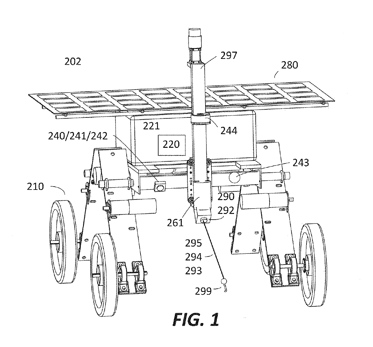
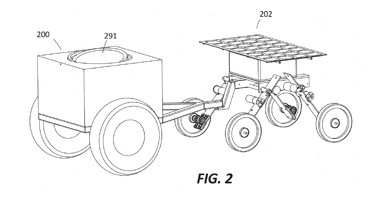
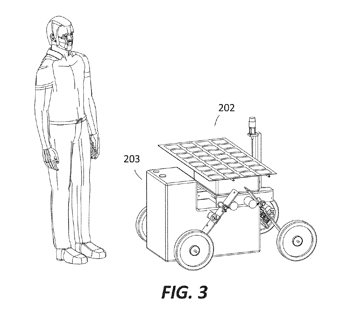
[0087]In this second embodiment, as shown in FIG. 4, the GURU 202 itself is configured so that it can move its body to align the focused energy on the non-crop 299. The GURU 202 is nimble enough and has enough ability to position and align its body to focus the energy on the selected non-crop 299. The GURU 202 can be any of a variety of configurations, but two envisioned options are set out herein. One, is the GURU 202 described above having the chassis, electric motors, the mobility apparatus (such as caterpillar tracks or wheels), onboard sensors, electronics, fuel cell, etc. and a means to connect the energy beam payload device 290 to the GURU 202. This device also can include a linkage chassis 116 and pivoted suspension 117. These two particular apparatus, along with other types of adjustable apparatus, allow the GURU 202 to have an adjustable height and a unique configurability. In this configuration there is the configurable ground utility robot 202 having an adjustable all-te...


PUM


Abstract

This invention is a configurable ground utility robot GURU having at least the following parts: an all-terrain mobile apparatus; a payload accepting apparatus; an onboard processor; at least one sensor that communicates with said onboard processor; at least one energy beam payload device connectable to the payload accepting apparatus, capable of creating an energy beam having enough power to elevate an internal temperature of a subject when the energy beam is focused on the subject and where the energy beam payload device communicates with the onboard processor and where the ground utility robot also has a computer program that at least performs the following functions: receives and interprets data from the at least one sensor; controls the mobile apparatus; focuses the at least one energy beam on the subject; and controls the beam strength and time duration.

Description

RELATED APPLICATION[0001]This application claims the benefit of U.S. provisional patent application Ser. No. 62 / 612,297, filed 2017 Dec. 29 and entitled AUTONOMOUS MODULAR GROUND UTILITY ROBOT SYSTEM which is incorporated herein by reference.FIELD OF THE INVENTION[0002]The current invention relates to a robot system that can include an energy collection system, an energy supply docking system, autonomous cooperative robots, payloads or apparatus attachable to the autonomous robots to perform functions or tasks and a control company or means to oversee and control robot reservations, robot delivery, operation and retrieval, to control energy collection and dissemination, and general maintenance and control of the robot system. This invention also relates to a human assisted machine learning system whereby humans are used to help train the robots to learn or perform functions. Finally, it relates to using the robots as cooperative or collaborative units whereby the robots can be used ...

Claims


Application Information

Patent Timeline
IPC IPC(8): A01D34/00A01M21/04B25J9/16G05D1/02
CPCA01D34/008A01M21/04B25J9/1697G05D1/0219G05D2201/0201Y02P60/12
Inventor CHRYSANTHAKOPOULOS, GEORGIOSFELSER, ADLAI
Owner DCENTIZED SYST LLC
Why Eureka
Try Eureka