System and method for vital signs detection

a technology of vital signs and systems, applied in the field of systems and methods for vital signs detection, can solve the problems of unobtrusive contact sensors for respiration measurements, unfavorable medical use, and unpleasant contact ppg measurement, and achieve the effects of reducing radiation energy sensed, high cost attraction, and reducing radiation intensity

Inactive Publication Date: 2019-07-04
KONINKLJIJKE PHILIPS NV
View PDF0 Cites 14 Cited by
  • Summary
  • Abstract
  • Description
  • Claims
  • Application Information

AI Technical Summary

Benefits of technology

[0027]According to embodiments of the present invention detector signals can be obtained, which may subsequently be used to determine one or more vital signs. For instance, a standard RGB camera with an NIR-blocking filter removed (as radiation detector) may be used in combination with a single light source, such as an LED (as radiation source). This creates a highly cost-attractive option for obtaining the detector signals.
[0028]The radiation source may be configured to emit radiation in said limited wavelength range around a wavelength peak and the radiation detector may further comprise a peak filter for suppressing the peak wavelength. Alternatively, such peak suppression filter may also be comprised in the radiation source, although this may reduce the radiation energy sensed by the detector. This increases the difference in relative pulsatility (due to the PPG signal) of the two wavelengths that are sensed by both wavelength sub-channels and, hence, provides more discriminative power to distinguish motion (which always has the same relative strength in the two channels) and PPG signals, i.e. further improves the motion-robust detection of vital signs.
[0029]In a further embodiment said radiation source is configured to flash at a detection rate of the radiation detector at a duty cycle and said radiation detector is configured to integrate radiation detected during said duty cycle. This further reduces the ambient light sensitivity of the system.

Problems solved by technology

Although contact PPG is regarded as a basically non-invasive technique, contact PPG measurement is often experienced as being unpleasant and obtrusive, since the pulse oximeter is directly attached to the subject and any cables limit the freedom to move and might hinder a workflow.
The same holds for contact sensors for respiration measurements, which may sometimes be practically impossible because of extremely sensitive skin (e.g. of patients with burns and preterm infants).
Therefore, remote photoplethysmographic systems and devices are considered unobtrusive and well suited for medical as well as non-medical everyday applications.
However, remote PPG devices typically achieve a lower signal-to-noise ratio.
There still are demanding situations, with severe motion, challenging environmental illumination conditions, or high required accuracy of the application, where an improved robustness and accuracy of the vital sign measurement devices and methods is required, particularly for the more critical healthcare applications.
Using cameras in the automotive field for vital signs detection has been considered, but motion robustness in this areas is complicated by the strong requirements to only use the already available NIR (near-infrared) illumination, which originates from a single LED light source (often emitting radiation around 850 nm).
The problem is that a camera registering the light reflected from the driver (e.g. the face) cannot distinguish between modulations caused by motion and modulations due to absorption changes of the skin caused by changing blood volume.
Although many attempts have been made to solve this issue, to date no satisfactory solution exists.

Method used


Image

  • System and method for vital signs detection
  • System and method for vital signs detection
  • System and method for vital signs detection

Examples


Embodiment Construction

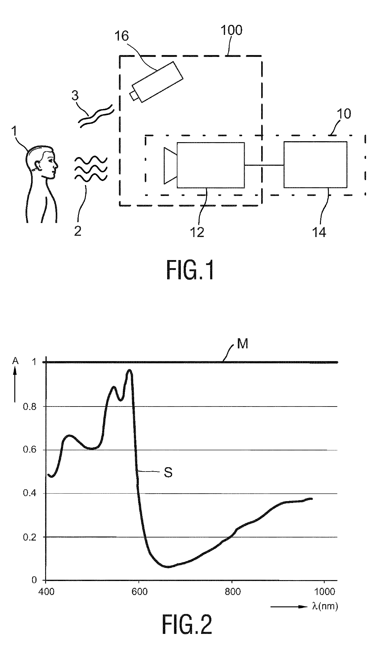
[0038]FIG. 1 shows a schematic diagram of a first embodiment of a device 10 and a system 100 according to the present invention. The device 10 comprises a radiation detector 12 for detecting radiation 2 reflected from a skin area of a subject 1, such as a patient, and for generating first and second detector signals from the detected radiation. The device 10 further comprises a vital signs detector 14 for detecting a vital sign (e.g. heart rate, SpO2, respiration rate, etc.) from a combination of said first and second detector signals.

[0039]The radiation detector 12 may e.g. be implemented as a photodetector or a camera, e.g. an RGB camera (optionally with an appropriate filter) and is configured to detect electromagnetic radiation from a skin area (e.g. the forehead, the cheeks, the hand, etc.) that is illuminated by radiation 3 of a limited wavelength range, e.g. by a radiation source 16, such as an LED (e.g. a near-infrared LED). The first detector signal generated by the radiati...


PUM


Abstract

The present invention relates to a system for vital signs detection. The system comprises a radiation source (16) for emitting radiation in a limited wavelength range for illuminating a skin area of a subject and a radiation detector (12), a radiation detector (12, 30, 40) for detecting radiation reflected from a skin area of a subject (1) in response to said illumination, and for generating first and second detector signals, the first detector signal representing radiation (2) reflected from the skin area of a subject in a first wavelength subrange of said limited wavelength range of radiation (3) and the second detector signal representing radiation in a second wavelength sub-range of said limited wavelength range of radiation different from said first wavelength sub-range, and a vital signs detector (14) for detecting a vital sign from a combination of said first and second detector signals by computing the difference between said first and second detector signals.

Description

FIELD OF THE INVENTION[0001]The present invention relates to a system and method for vital signs detection.BACKGROUND OF THE INVENTION[0002]Vital signs of a person, for example the heart rate (HR), the respiration rate (RR) or the arterial blood oxygen saturation, serve as indicators of the current state of a person and as powerful predictors of serious medical events. For this reason, vital signs are extensively monitored in inpatient and outpatient care settings, at home or in further health, leisure and fitness settings.[0003]One way of measuring vital signs is plethysmography. Plethysmography generally refers to the measurement of volume changes of an organ or a body part and in particular to the detection of volume changes due to a cardio-vascular pulse wave traveling through the body of a subject with every heartbeat.[0004]Photoplethysmography (PPG) is an optical measurement technique that evaluates a time-variant change of light reflectance or transmission of an area or volum...

Claims


Application Information

Patent Timeline
Patent Type & Authority Applications(United States)
IPC IPC(8): A61B5/00
CPCA61B5/0075A61B5/0077A61B5/02433A61B5/14552A61B5/6888A61B5/6889A61B5/6893A61B5/7214A61B5/18
Inventor DE HAAN, GERARD
Owner KONINKLJIJKE PHILIPS NV
Why Eureka
Try Eureka