Curing light device assembly

Inactive Publication Date: 2019-07-04
GARRISON DENTAL SOLUTIONS
View PDF4 Cites 1 Cited by
  • Summary
  • Abstract
  • Description
  • Claims
  • Application Information

AI Technical Summary

Benefits of technology

The patent describes a curing light assembly with a housing, a base for supporting the housing, and a light source. The assembly also includes a controller for operating the light source and a sensor for detecting the light emitted. The sensor can detect the light emitted when the housing is supported in a storage position. The controller calibrates the light source based on the light detected by the sensor. The actuatable input device can be a user-actuated switch or a sensor on the housing or base for detecting when the housing is supported in the storage position. The method of calibratin using the closed loop feedback or open loop calibration process powering the light source in response to a signal such as a sensor or switch. Overall, the curing light device provides a convenient way to calibrate the light source.

Problems solved by technology

First, all LED lights decay over time and, therefore, even when higher power LEDs are available the amount of heat delivered to the tooth may not be easily predicted or accurate.
With more powerful LEDs the need for greater accuracy is more important because there is a tendency by some to overcompensate when the proper curing is not first achieved—and with more powerful LEDs, overcompensation could elevate the temperature of the treated tooth to an undesired level, which can harm the vitality of the tooth pulp.
In some cases, there is the possibility due to misalignment of the curing light the elevated temperatures can cause unintended direct exposure of tongue, cheek, or gingival tissues that in turn can cause painful and in some cases, severe, burns to those irradiated tissues.

Method used


Image

  • Curing light device assembly
  • Curing light device assembly
  • Curing light device assembly

Examples


Embodiment Construction

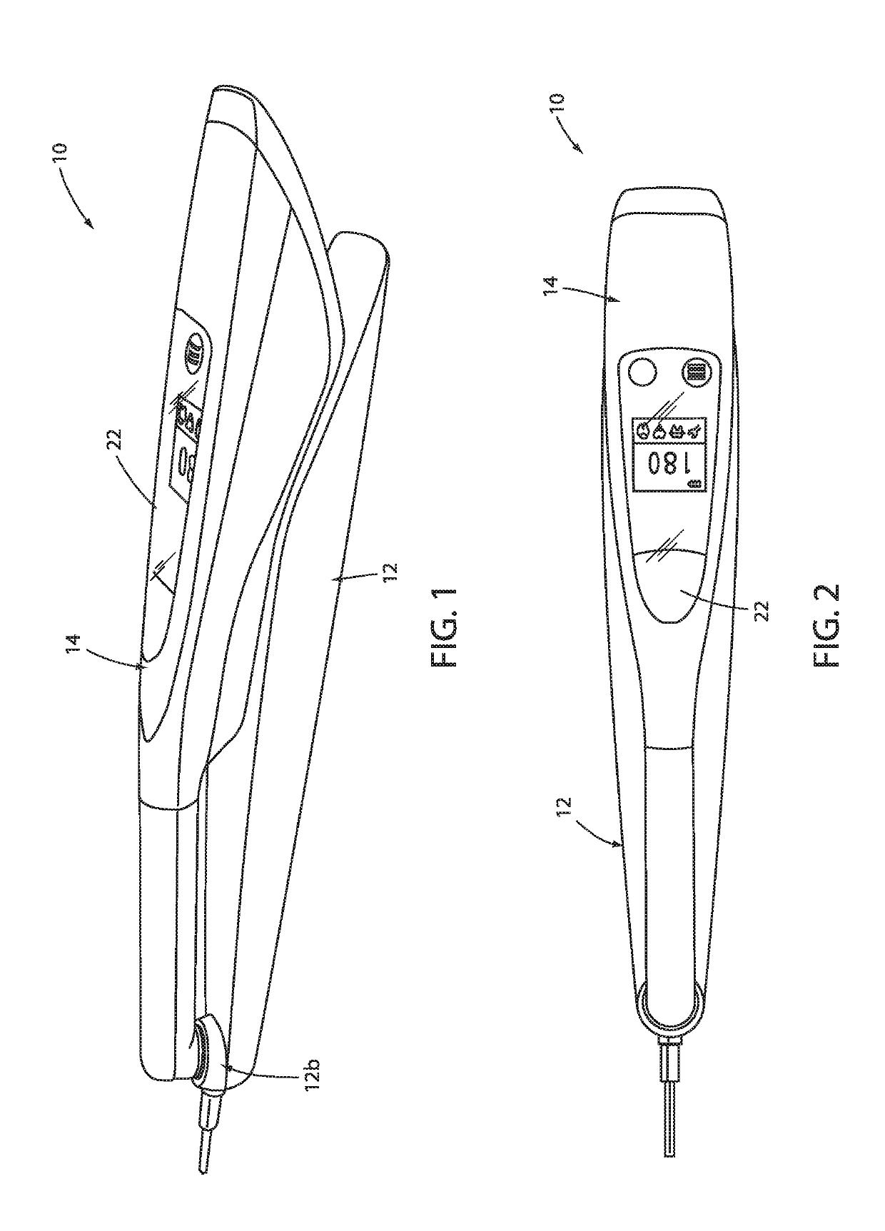
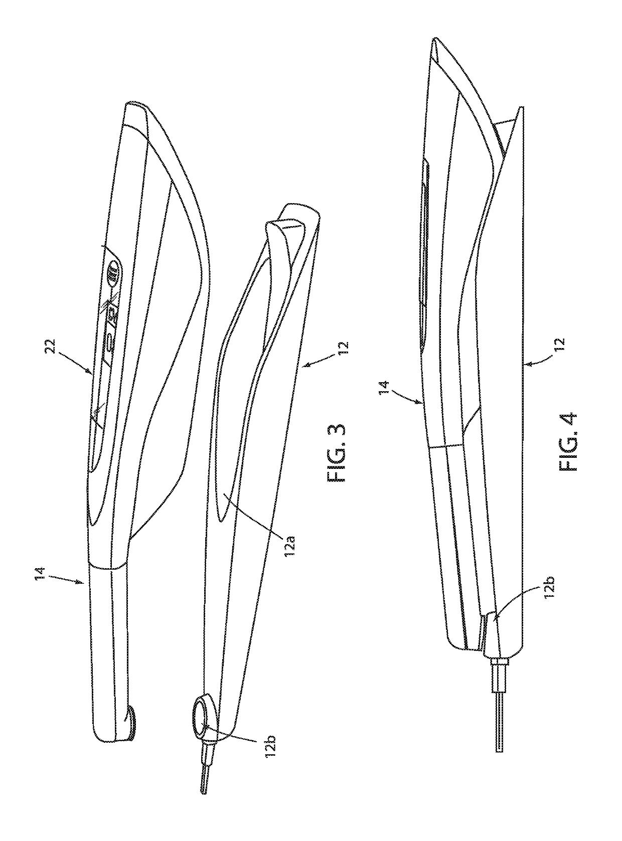
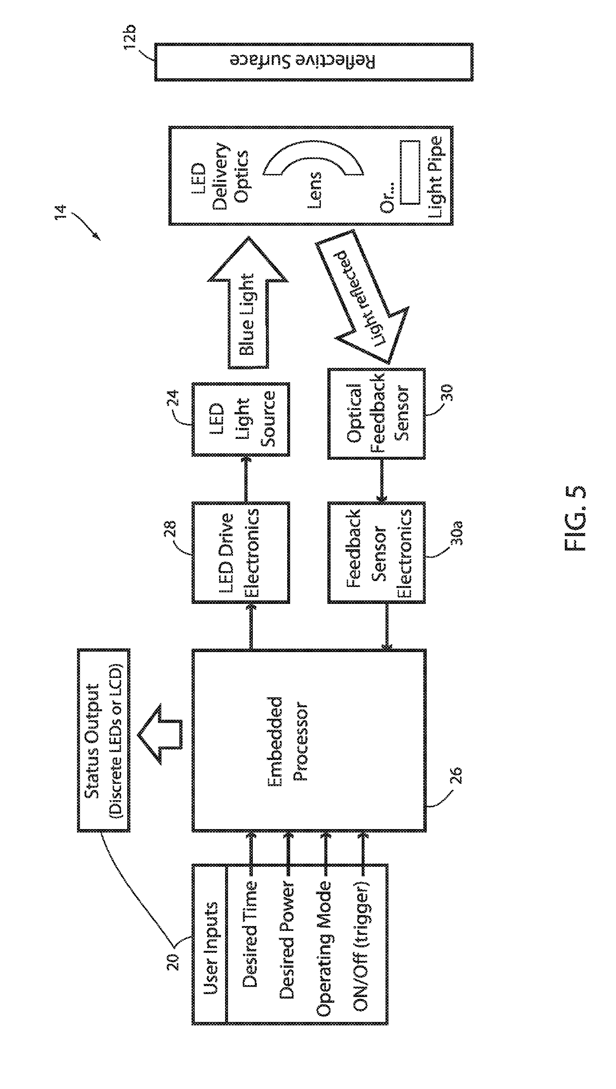
[0032]Referring to FIG. 1, the numeral 10 generally depicts a curing light device assembly with a base 12 and a curing light device or instrument 14, which can provide light to a composite material during a cure. As will be more fully described below, curing light device 14 may be used to cure a light activated composite material, such as by polymerizing monomers into durable polymers, and further may include a closed loop feedback control of its light output. Further, as will be more fully described below, assembly 10 is configured to calibrate the light of curing light device 14 when the curing light device is located in its stored position within base 12.

[0033]Curing light device 14 may be a standalone device, such as a portable handheld wand having a battery power source and controls, or a component of a curing system having a base unit to which the curing light device 14 is tethered and receives power therefrom and optionally control signals therefrom. A variety of fields may b...


PUM


Abstract

A curing light assembly includes a housing, a base for supporting the housing in a storage position, a light source supported by the housing, and a controller configured to operate the light source. The light assembly further includes a light sensor in communication with the controller, which light sensor is operable to detect light emitted from the light source when the housing is supported in the storage position, and with the controller configured to calibrate the light source based on light detected by the light sensor from the light source when the housing is supported in the storage position.

Description

TECHNICAL FIELD AND BACKGROUND OF THE DISCLOSURE[0001]The present disclosure relates to a curing light device, and more specifically to a curing light device that may be used to cure dental composites.[0002]Dental curing LED light devices used to cross-polymerize (i.e. harden) the resin used in modern composite fillings for teeth have been received with much success. With the advancements in LED technology, the power output from curing light devices has increased over the years. While an optical power of about 200 to 300 mW / cm2 was typical a decade ago, the power associated with current designs often exceeds 2000 mw / cm2.[0003]With the ensuing trend toward much higher power dental curing lights, intended to solve various issues of “under cure” and also to greatly reduce the time required to achieve full cure of a placed composite filling, several temperature related challenges have become prevalent. First, all LED lights decay over time and, therefore, even when higher power LEDs are...

Claims


Application Information

Patent Timeline
IPC IPC(8): A61C13/15H05B33/08F21V7/00H05B44/00
CPCA61C19/004H05B33/0893F21V7/0075F21Y2115/10A61C1/0015H05B45/14H05B45/58
Inventor PETERSON, STEVEN H.
Owner GARRISON DENTAL SOLUTIONS
Why Eureka
Try Eureka