

Device for suctioning bodily fluids and for supplying a substance
a technology for bodily fluids and devices, applied in the direction of positive displacement liquid engines, machines/engines, catheters, etc., can solve the problems of devices, which serve, and the operation of such devices is often laborious for the user, and the supply of substances, which is a considerable volume and weigh
- Summary
- Abstract
- Description
- Claims
- Application Information
AI Technical Summary
Benefits of technology
Problems solved by technology
Method used
Image

Examples
first embodiment
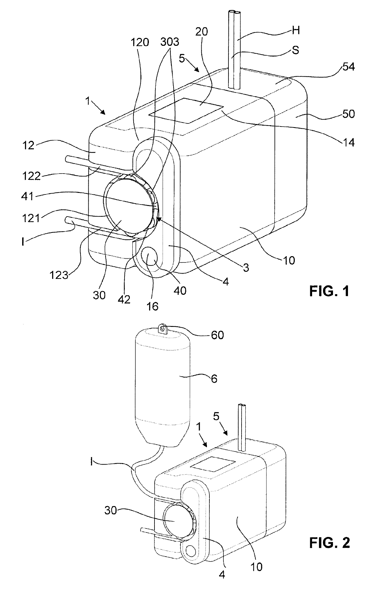
[0048]As is clearly apparent in FIG. 1, the device of the first embodiment according to the invention of FIGS. 1 to 4 has a pump unit housing 1 with a fluid-collecting container 5 which can be connected up thereto.
[0049]The pump unit housing 1 has an overall substantially cuboid form. In FIGS. 1 and 2, a top wall 14, a front wall 10 and a side wall 12 of the pump unit housing 1 are respectively discernible. The side wall 12 has in its corner region, where it is connected to the front wall 10, an indentation 120, which extends along the entire height of the side wall 12.
[0050]The fluid-collecting container 5 likewise has an overall substantially cuboid form. In FIGS. 1 and 2 can respectively be seen a top wall 54 and a front wall 50. If the fluid-collecting container 5 is properly connected up to the pump unit housing 1, as is shown in FIGS. 1 and 2, it forms together with this same an overall substantially cuboid shape with rounded outer edges and outer corners. The external walls o...
second embodiment
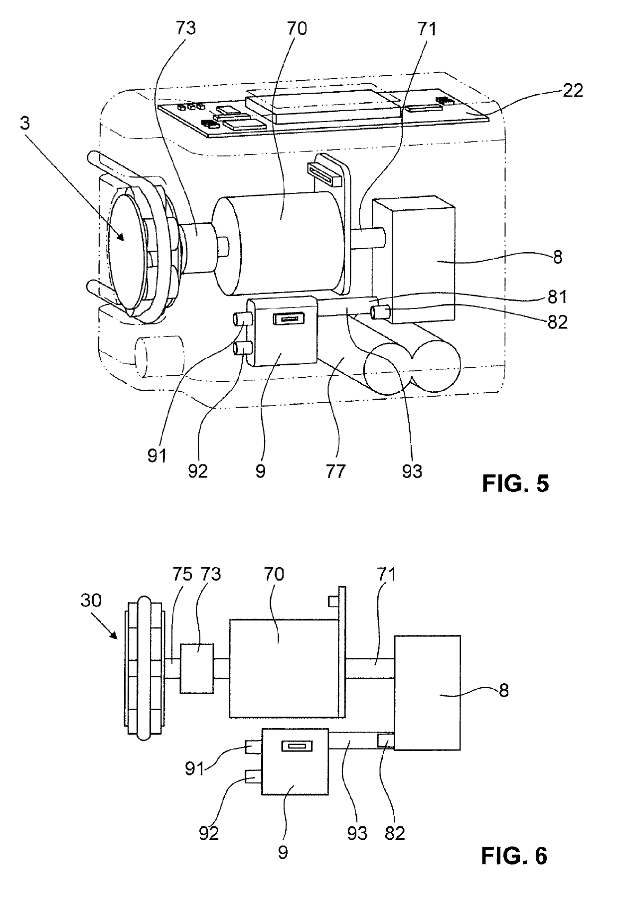
[0069]The second embodiment according to the invention, shown in FIGS. 5 and 6, is configured the same as the embodiment of FIGS. 1 to 4, apart from some few differences which are set out below.
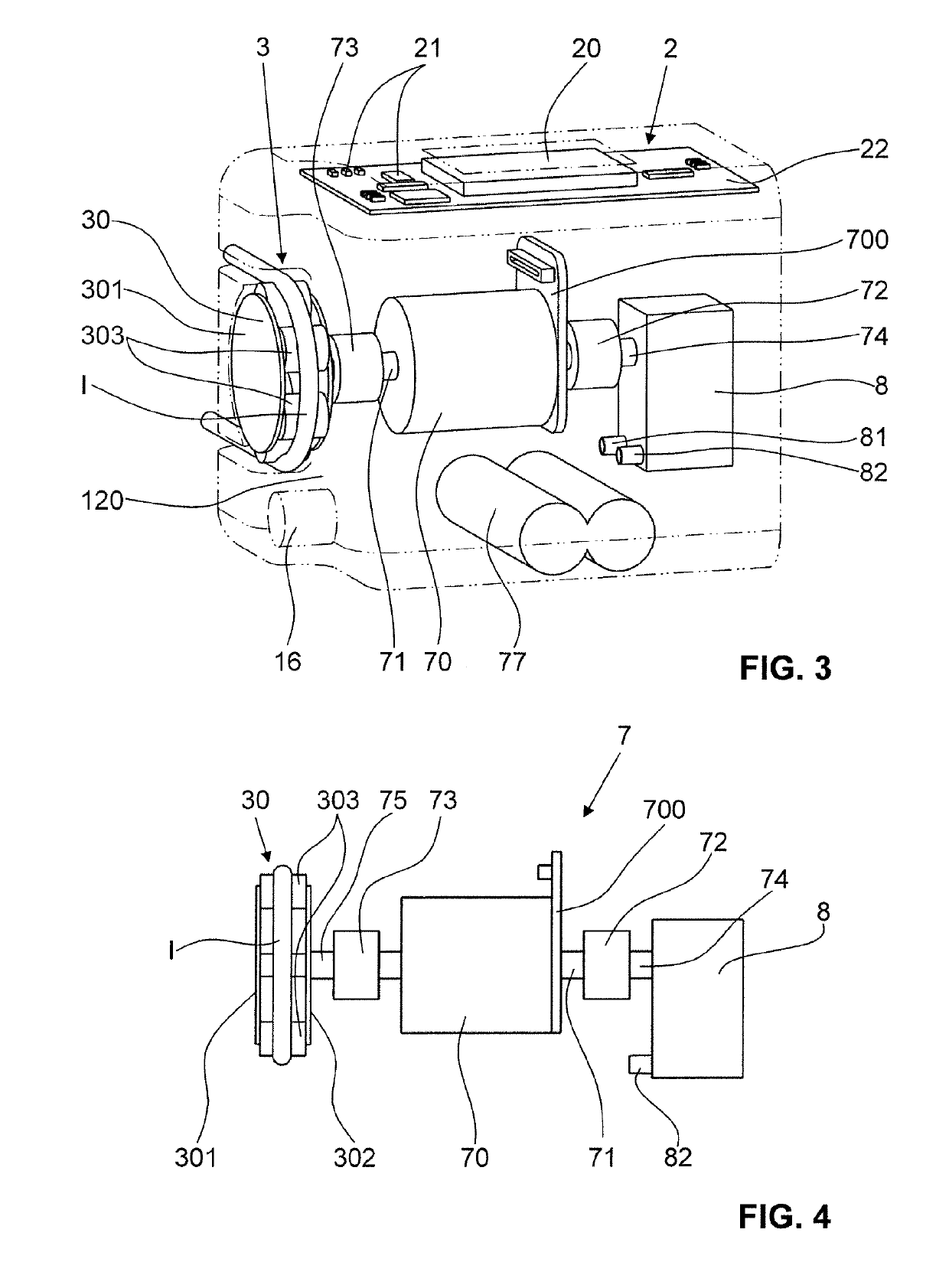
[0070]In contrast to the embodiment of FIGS. 1 to 4, that of FIGS. 5 and 6 has only a single freewheel 73, which connects the motor shaft 71 to that drive shaft 75 which drives the pump head 30. The drive of the diaphragm pump 8 is realized directly via the motor shaft 71. It is thereby possible to drive the two pumps 3 and 8 simultaneously, so that both a secretion aspiration through the secretion line S and a supplying of instillation liquid through the instillation line I can occur at the same time. When the rotational direction of the motor 70 is reversed, because of the freewheel 73 only the diaphragm pump 8, however, is driven.
[0071]In order nevertheless to enable, in the simultaneous operation of the diaphragm pump 8 and the peristaltic pump 3, any chosen adjustment of the vacuum preva...
third embodiment
[0073]A third embodiment according to the invention is shown in FIGS. 7 to 9. The device of this embodiment comprises a pump unit housing 1′, shown in FIG. 7, to which a fluid-collecting container 5′, shown in FIGS. 8 and 9, is connectable.
[0074]Here too, the pump unit housing 1′ has an overall substantially cuboid form having a front wall (not shown in FIG. 7), a rear wall 11′, a first side wall 12′ and a second side wall 13′, as well as a top wall 14′ and a bottom wall 15′. The front wall and the rear wall 11′ each have a wall edge, which wall edges protrude beyond the first side wall 12′ arranged therebetween. The fluid-collecting container 5′ is held between these wall edges and can thereby be fastened easily, but nevertheless in a secure and protected manner, to the pump unit housing 1′.
[0075]For the hanging and holding of the fluid-collecting container 5′ on the pump unit housing 1′, on the pump unit housing 1′ are provided receiving hooks 190′, in which correspondingly config...
PUM
 Abstract
Description
Claims
Application Information