Hydraulic unit

a technology of hydraulic pump and screw groove, applied in the direction of machines/engines, liquid fuel engines, servomotors, etc., can solve the problems of contamination caused by foreign objects entering the screw groove, the conventional constitution of screwing the hydraulic pump and the suction strainer,

Active Publication Date: 2019-07-04
SHIMADZU CORP
View PDF7 Cites 0 Cited by
  • Summary
  • Abstract
  • Description
  • Claims
  • Application Information

AI Technical Summary

Benefits of technology

[0014]According to the disclosure, a structure can be achieved, without causing increase in man-hours needed for processing or man-hours needed for assembly, in which a suction strainer does not fall off out of a hydraulic pump or a return pipe does not fall off out of a manifold so that a flow path of a hydraulic fluid can be ensured.

Problems solved by technology

However, the conventional constitution of screwing the hydraulic pump and the suction strainer has the problems described below.
Then, while conducting the screwing, there is also concern that a contamination caused by foreign objects entering the screw groove is generated.
Furthermore, in the hydraulic unit described above, conventionally, the connection of the manifold and the return pipe is also conducted by screwing, and in the connection of the manifold and the return pipe, there are also problems similar to the problems in the connection of the hydraulic pump and the suction strainer described above.

Method used


Image

  • Hydraulic unit
  • Hydraulic unit
  • Hydraulic unit

Examples


Embodiment Construction

[0020]One embodiment of the disclosure is described below with reference to FIG. 1 through FIG. 5.

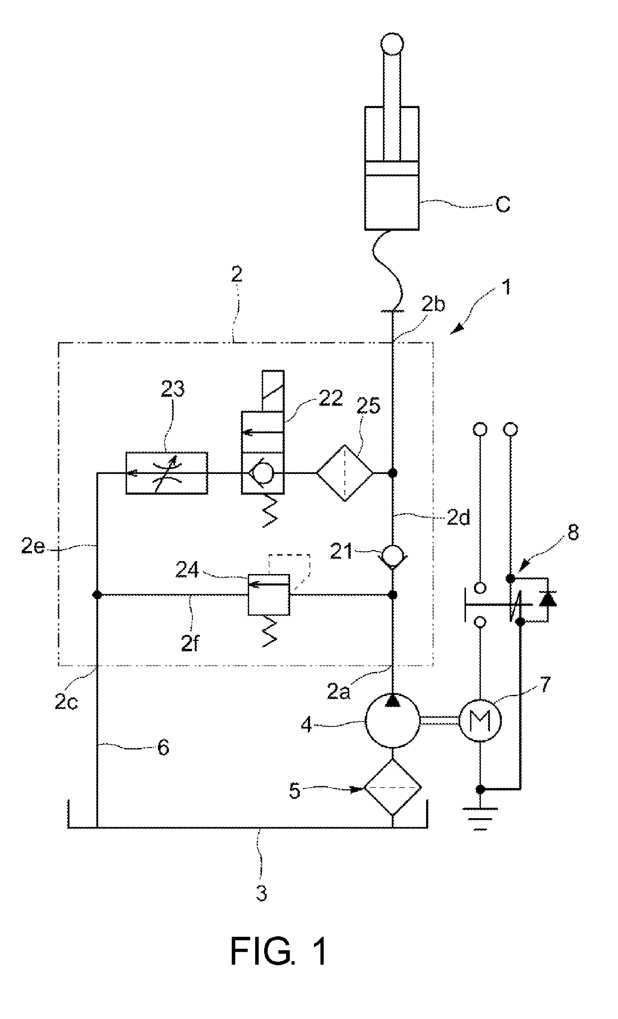
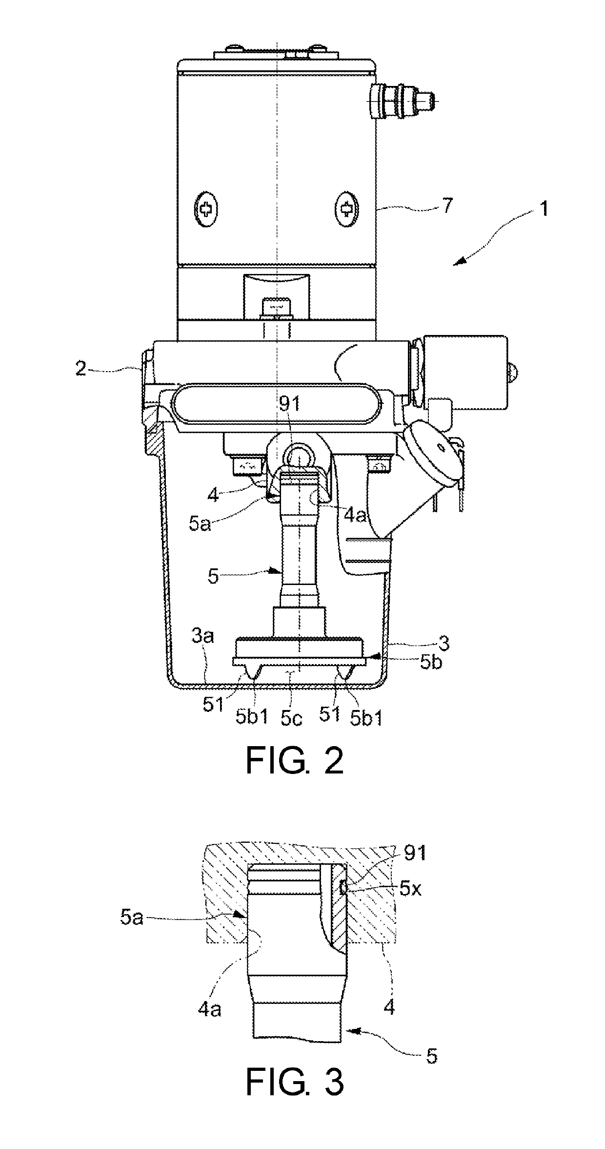
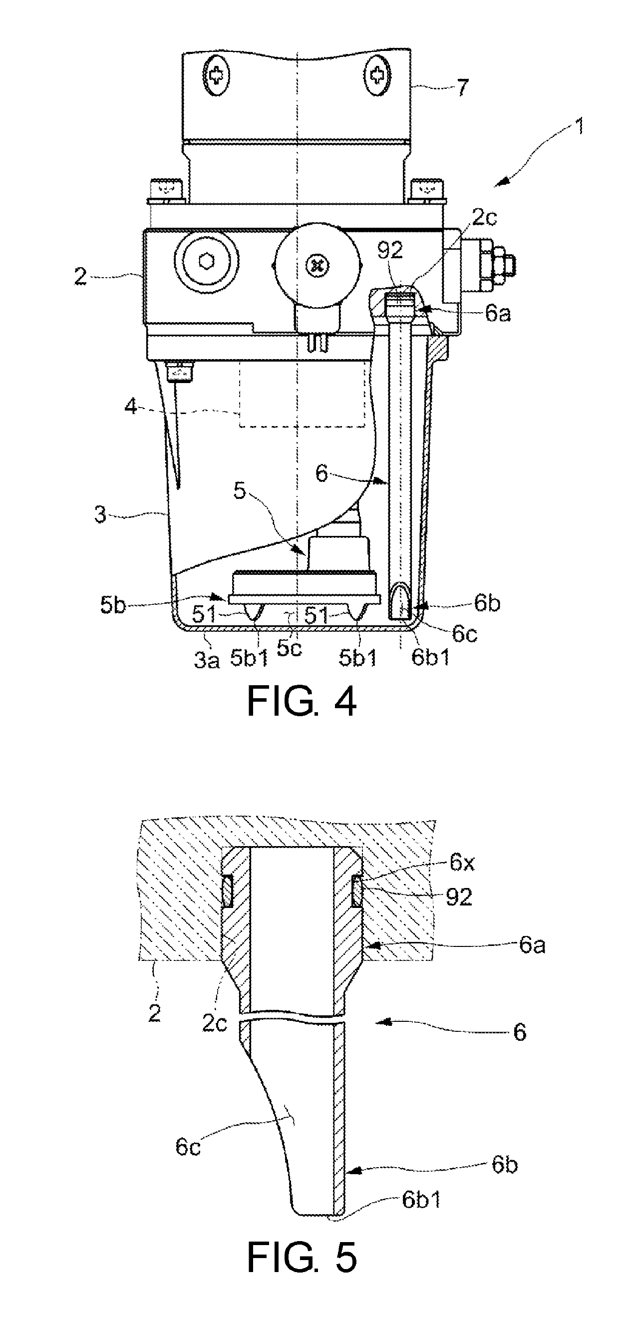
[0021]A hydraulic unit 1 of the embodiment supplies a hydraulic fluid to a cylinder C which constitutes an actuator for lifting and lowering a loading platform of a logistics machine, such as a fork lift, which is a driven object, and as shown in FIG. 1, FIG. 2 and FIG. 4, includes: a manifold 2 which forms a hydraulic circuit; a tank 3 which is joined to the manifold 2; a hydraulic pump 4 which suctions the hydraulic fluid in the tank 3 and supplies the hydraulic fluid to the manifold 2; a suction strainer 5 in which the base end portion 5a is fitted into the hydraulic pump 4; and a return pipe 6 in which the base end portion 6a is fitted into the manifold 2.

[0022]The manifold 2 includes, as shown in FIG. 1, a hydraulic fluid inflow port 2a which receives a supply of the hydraulic fluid from the hydraulic pump 4; a hydraulic fluid supply port 2b which allows the hydraulic fluid in or o...


PUM


Abstract

A hydraulic unit is provided with: a manifold which forms a hydraulic circuit; a tank which is joined to the manifold; and a hydraulic pump which suctions hydraulic fluid in the tank and supplies the hydraulic fluid to the manifold, wherein the base end portion of a suction strainer is fitted into the hydraulic pump, and the suction strainer has such a shape that the base end portion of the suction strainer is not separated from the hydraulic pump in a state where the leading end portion of the suction strainer is in contact with the tank and an opening through which the hydraulic fluid is introduced from the tank is provided at the leading end portion.

Description

BACKGROUND OF THE DISCLOSURETechnical Field[0001]The disclosure relates to a hydraulic unit constituting a hydraulic circuit for lifting and lowering a loading platform of a logistics machine.Related Art[0002]Conventionally, a hydraulic unit is widely used which includes: a manifold which have a check valve, a switching valve and a relief valve built-in; a tank which is joined to the manifold; a hydraulic pump which suctions a hydraulic fluid in the tank and supplies the hydraulic fluid to the manifold; a suction strainer in which a base end portion is connected to the hydraulic pump; and a return pipe in which the base end portion is connected to the manifold. Such a hydraulic unit constitutes a hydraulic circuit which supplies and recirculates the hydraulic fluid between the hydraulic circuit and an actuator which is connected to the manifold (for example, see patent literature 1).[0003]In such a hydraulic circuit, when the switching valve is in a first state, the hydraulic fluid ...

Claims


Application Information

Patent Timeline
Patent Type & Authority Applications(United States)
IPC IPC(8): B66F9/22F15B1/26F15B11/00F04B53/20
CPCB66F9/22F15B1/26F15B11/003F04B53/20F04B53/22F15B21/041F15B2211/20515F15B2211/20538F15B2211/30505F15B2211/31529F15B2211/40515F15B2211/40576F15B2211/411F15B2211/41581
Inventor OTO, MASAOHIGASHI, HIDEKINISHIDA, HIROYUKI
Owner SHIMADZU CORP
Why Eureka
Try Eureka