Eureka AIR delivers breakthrough ideas for toughest innovation challenges, trusted by R&D personnel around the world.

Transporting system for transporting products

Active Publication Date: 2019-07-11
MARCHESINI GROUP SPA
View PDF0 Cites 0 Cited by
  • Summary
  • Abstract
  • Description
  • Claims
  • Application Information

AI Technical Summary

Benefits of technology

The present invention aims to provide a new transport system that can ensure the stability of the carriage and the product being transported when the carriage moves from a straight section to a curved section. This new system should also reduce wear and tear on the rollers to a minimum.

Problems solved by technology

A first drawback of this transport system consists in the stability of the carriage during the passage thereof from a straight portion to a curved portion, as some of the rollers can lose contact with the internal wall or external wall of the guide rail and therefore the other rollers are subjected to a greater rolling friction.
The onset of these circumstances not only influences the stability of the carriage, with repercussions on the correct orientation and positioning of the product to be transported, but also determines more rapid wear on the rollers.
Firstly, problems can arise concerning the stability of the carriage at the change of direction of the carriage of the guide rail from the straight portion to the curved portion, as there is a moment of transition in which the rollers of the first group of rollers lose contact with the internal walls and the external walls of the guide rail in the final part of the straight portion, while the rollers of the second group of rollers must instead gain contact with the two walls at the start of the curved portion. The same drawback occurs during the change of direction of the guide rail from the curved portion to the straight portion.
The onset of these circumstances can lead to an increase in stresses on the rollers of the two groups, with the consequence that the reduction in the degree of wear is not as good as was hoped for.

Method used


Image

  • Transporting system for transporting products
  • Transporting system for transporting products
  • Transporting system for transporting products

Examples


Embodiment Construction

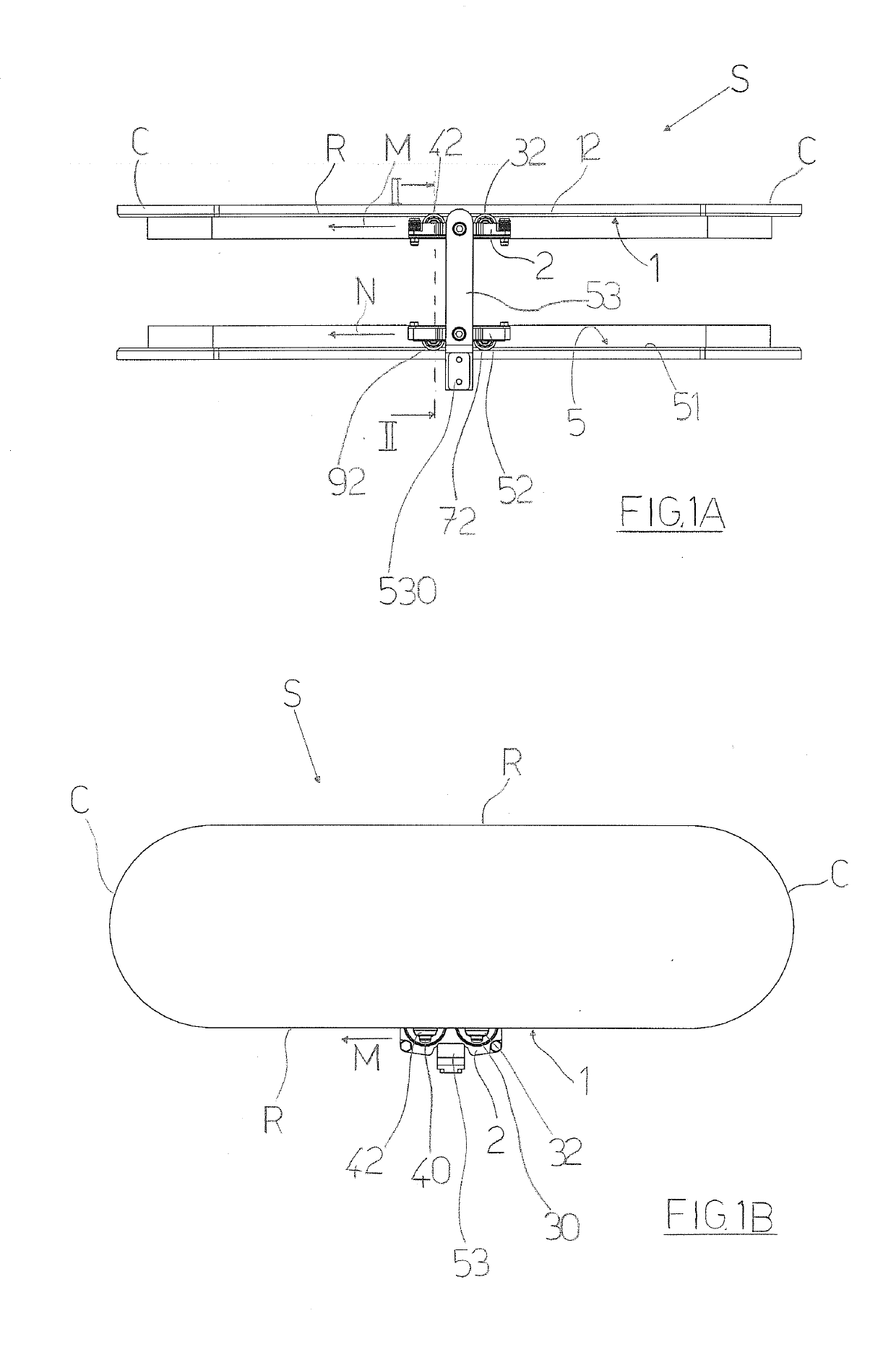
[0037]With reference to the accompanying tables of drawings, reference letter (5) denotes the transport system for transporting products of the present invention. The transport system (5) comprises at least a guide rail (1) and at least a carriage (2) for transport of at least a relative product.

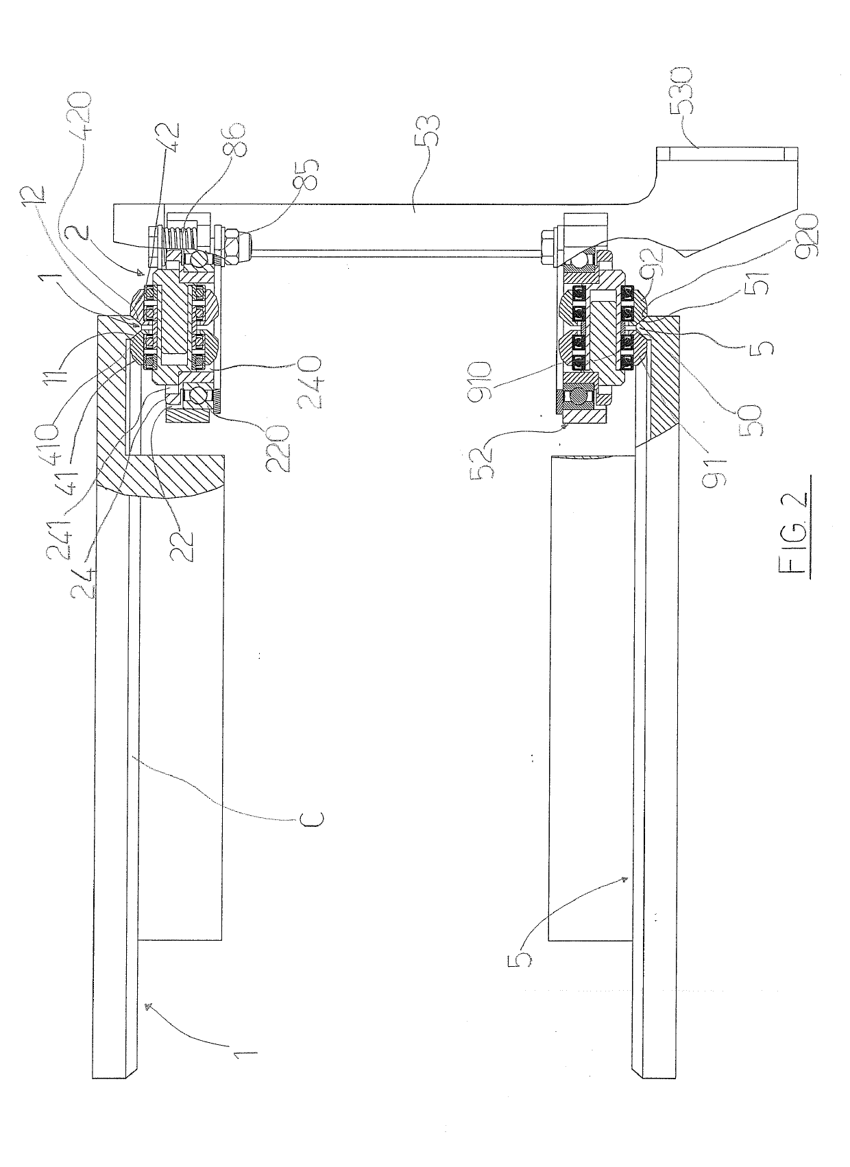
[0038]The guide rail (1) has a loop-wound pathway comprising straight portions (R) and curved portions (C) for connecting the straight portions (R) (see for example FIGS. 1A and 1B), the guide rail (1) being conformed so as to have an internal rolling wall (11) and an external rolling wall (12) (visible for example in FIG. 2 in the sectioned part, upper on the left); the carriage (2) being moved (for example via activating means comprising linear motors that are not illustrated) with a movement direction (M) along the loop-wound pathway of the guide rail (1).

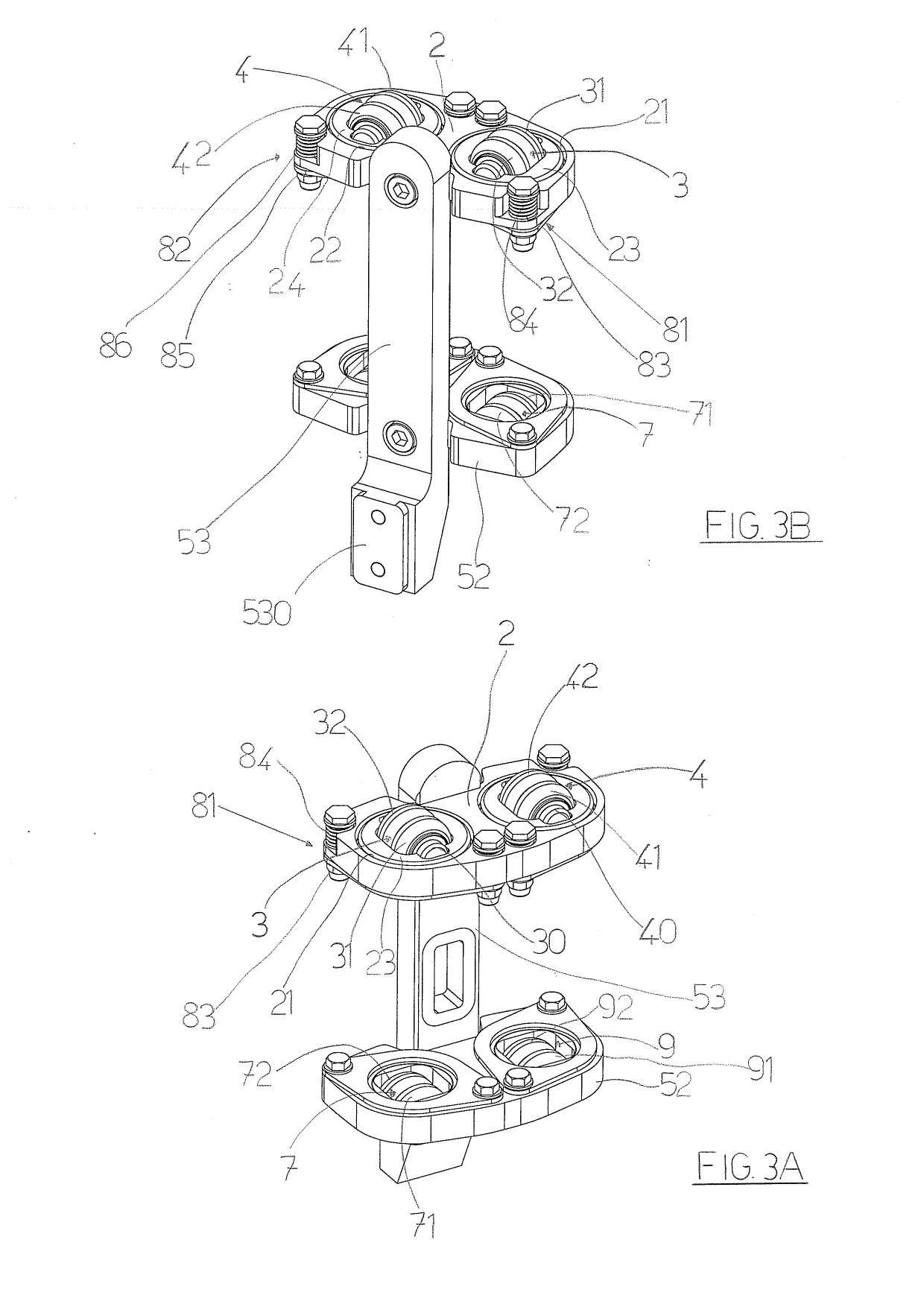
[0039]The transport system (S) further comprises a first pair (3) of rollers (31, 32) and a second pair (4) of rollers (41, 42) predisp...


PUM


Abstract

A transport system includes a guide rail having a loop-wound pathway with straight portions and curved portions linking the straight portions. A carriage is movable along the guide rail, a first and a second shaft being mounted on the carriage transversely to the carriage movement direction. A first pair of rollers are mounted rotatably on the first shaft so that a first roller contacts the internal wall of the guide rail and a second roller contacts the external wall of the guide rail. A second pair of rollers mounted rotatably on the second shaft include a first roller in contact with the internal wall of the guide rail and a second roller in contact with the external wall. The first and the second shaft are mounted on the carriage for pivoting about an axis perpendicular to the carriage.

Description

FIELD OF THE INVENTION[0001]The present invention relates to a transport system for transport of products.DESCRIPTION OF THE PRIOR ART[0002]In the sector of automatic work, production and / or packaging systems, there is a known need to transport products, objects, articles, components etc. along a predefined pathway so as to be able to know, exactly and precisely, the position and orientation thereof in relation to specific working steps which are to be carried out.[0003]A known transport system used for transport of products comprises at least a mobile carriage, for transport of at least a relative product, and at least a guide rail having a loop-wound pathway along which the carriage is guided and moved, by relative motor means, such as for example linear motors, or loop-wound conveyor belts on relative drive pulleys.[0004]The guide rail is conformed so as to exhibit an internal wall and an external wall; usually the internal wall and the external wall are mutually inclined and hav...

Claims


Application Information

Patent Timeline
IPC IPC(8): B65G17/20
CPCB65G17/20B65G39/20B65G9/002B65G9/008B65G21/22B61B13/00
Inventor MONTI, GIUSEPPE
Owner MARCHESINI GROUP SPA
Why Eureka
Eureka Blog
Learn More