Multi-stage scroll vacuum pumps and related scroll devices

a vacuum pump and multi-stage technology, applied in the direction of rotary/oscillating piston pump components, machines/engines, liquid fuel engines, etc., can solve the problems of limited to a single stage of compression, difficult and expensive manufacturing of oil free or oil less scroll type compressors and vacuum pumps, and links cannot be used in an oil free piece of equipment. , to achieve the effect of minimizing space requirements and high gas pressur

Active Publication Date: 2019-07-11
AIR SQUARED
View PDF0 Cites 10 Cited by
  • Summary
  • Abstract
  • Description
  • Claims
  • Application Information

AI Technical Summary

Benefits of technology

[0055]It is, therefore, the principal object of this invention to provide a multi-stage scroll vacuum pump or gas compressor, that may provide various scrolls arranged in parallel, and/or in series, in order to attain the generation of very high vacuums, or very high gas pressure,...

Problems solved by technology

In general, they have been limited to a single stage of compression due to the complexity of two or more stages, formed for compression, and for operation.
Oil free or oil less scroll type compressors and vacuum pumps have difficult and expensive manufacturing, due to the high precision of the scroll in each pump and compressor.
Such links can not be used in an oil free piece of equipment b...

Method used


Image

  • Multi-stage scroll vacuum pumps and related scroll devices
  • Multi-stage scroll vacuum pumps and related scroll devices
  • Multi-stage scroll vacuum pumps and related scroll devices

Examples


Embodiment Construction

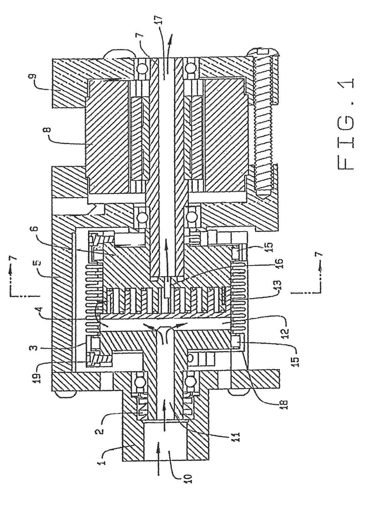
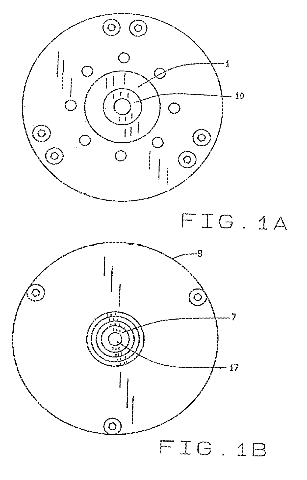
[0156]In referring to the drawings, FIG. 1 shows a cross-sectional view of the single stage spinning or co-rotating scroll vacuum pump / compressor design of this invention. It includes the various components as previously identified, such as the driven scroll housing 1, provided with a shaft seal 2, and a driven scroll 3. Item 4 provides a bellows that surrounds the driven scroll, that seals the generated pressures, whether it be derived from a vacuum pump, or a compressor that generates high pressure, in its operations: A drive scroll housing 5 surrounds these operative components. The drive scroll 6 has its various scrolls interconnected with the driven scroll 3, as shown. A drive shaft 7, connects with the drive scroll 6, to provide for its rotation relative to the driven scroll, and the drive shaft 7 is rotated by means of the motor 8, as can be noted. There is a back motor bracket 9 that is provided for mounting of the motor, and its pump / compressor, in its configured assembly.

[...


PUM


Abstract

A multi-stage vacuum pump, expander, or compressor, that incorporates one or more stages of a fixed scroll(s) and orbiting scroll(s) that operates simultaneously. The motor drives the orbiting scroll(s) within the structure, and the various fixed and orbiting scrolls are arranged for either parallel generation of a vacuum or high pressure gas, or arranged in series for generating of a significantly high vacuum or gaseous pressure, or a combination of parallel arranged and series arranged fixed and orbiting scrolls may be embodied within the structure, operated by a single motor means, in order to attain the high efficiencies of operation as a vacuum pump, or a gaseous compressor, during its functioning. The various combinations of orbiting and fixed scrolls, when arranged as aforesaid, can be reduced in size, or miniaturized, and used in conjunction with small appliances, or even in hand-held instruments, as for example, for use in conducting mass spectrometry, or for other purposes. The actual structure of the multi-stage devices can include the fixed and orbiting scrolls adjacent the motor, or the singular motor may be located intermediate various stages of the formed vacuum pump/compressor, in its assembly.

Description

CROSS REFERENCE TO RELATED APPLICATION[0001]This non-provisional patent application claims priority to the provisional patent application having Ser. No. 62 / 179,437, filed on May 7, 2015; and this non-provisional patent application claims priority to the non-provisional patent application having Ser. No. 14 / 544,874, filed on Feb. 27, 2015, which claims priority as a continuation-in-part patent application to the patent application having Ser. No. 13 / 987,486, filed on Jul. 30, 2013, now U.S. Pat. No. 9,028,230, which claims priority to the non-provisional patent application having Ser. No. 13 / 066,261, filed on Apr. 11, 2011, now U.S. Pat. No. 8,523,544, which claims priority to the provisional patent application having Ser. No. 61 / 342,690, filed on Apr. 16, 2010, which claims priority to the non-provisional patent application having Ser. No. 12 / 930,140, filed on Dec. 29, 2010, now U.S. Pat. No. 8,668,479, which claims priority to the provisional patent application having Ser. No. 61 / ...

Claims


Application Information

Patent Timeline
IPC IPC(8): F04C23/00F04C18/02F04C29/00F04C25/02F04C23/02
CPCF04C23/001F04C18/0284F04C29/0085F04C25/02F04C23/02F04C18/0215F04C18/0223F04C29/005F04C2240/20F04C2240/603F04C2240/30F04C23/008F04C27/005
Inventor SHAFFER, ROBERT W.SHAFFER, BRYCE R.
Owner AIR SQUARED
Why Eureka
Try Eureka