
Facial authentication systems and methods utilizing time of flight sensing

a facial authentication and time flight technology, applied in the field of facial authentication systems, can solve the problems of requiring a significant amount of image processing power in the device, consuming more power during the authentication process, and systems are vulnerable to spoofing attempts made by unauthorized users of the device, so as to improve the security and accuracy of facial authentication techniques

Active Publication Date: 2019-07-11
STMICROELECTRONICS SRL
View PDF2 Cites 26 Cited by
  • Summary
  • Abstract
  • Description
  • Claims
  • Application Information

AI Technical Summary

Benefits of technology

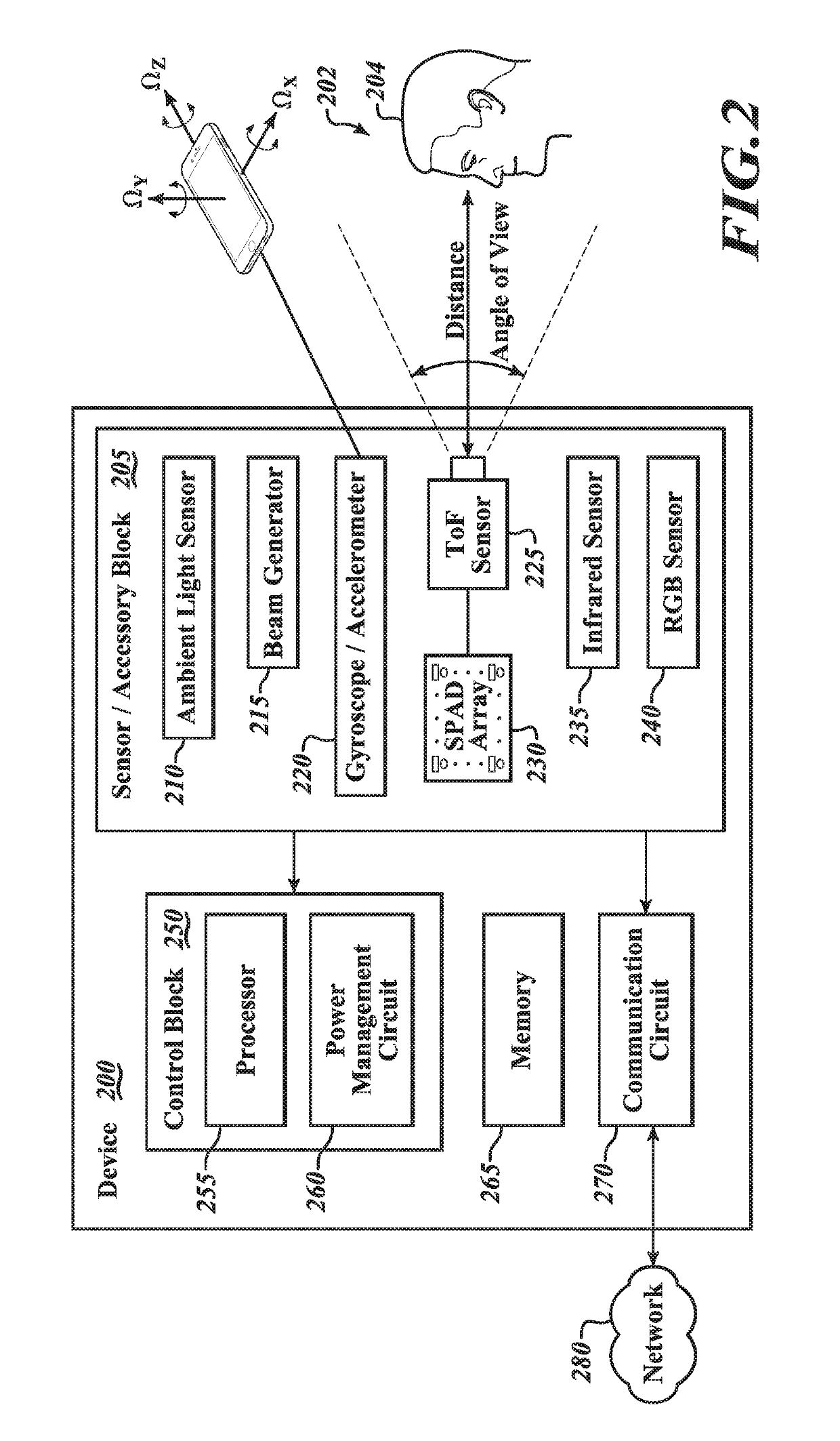
The patent text discusses a facial authentication device and method that uses a time of flight sensor and an ambient light sensor to improve power consumption efficiency. This technology helps to maintain low cost in manufacturing electronic devices and provides improved precision in detecting a user's face during facial recognition / authentication while consuming reduced power of the device.

Problems solved by technology

Such facial authentication systems require a significant amount of image processing power in the device. and accordingly consume more power during the authentication process.
Further, some systems are vulnerable to spoofing attempts made by unauthorized users of the device.
Employing RGB cameras, IR cameras, image sensors using structured light, stereoscopic cameras or other sensors in the electronic device may not help overcome these fraudulent attempts to bypass the facial authentication process, and having numerous sensor modules embedded in the device will also drive up the cost of the device.

Method used


Image

  • Facial authentication systems and methods utilizing time of flight sensing
  • Facial authentication systems and methods utilizing time of flight sensing
  • Facial authentication systems and methods utilizing time of flight sensing

Examples


Embodiment Construction

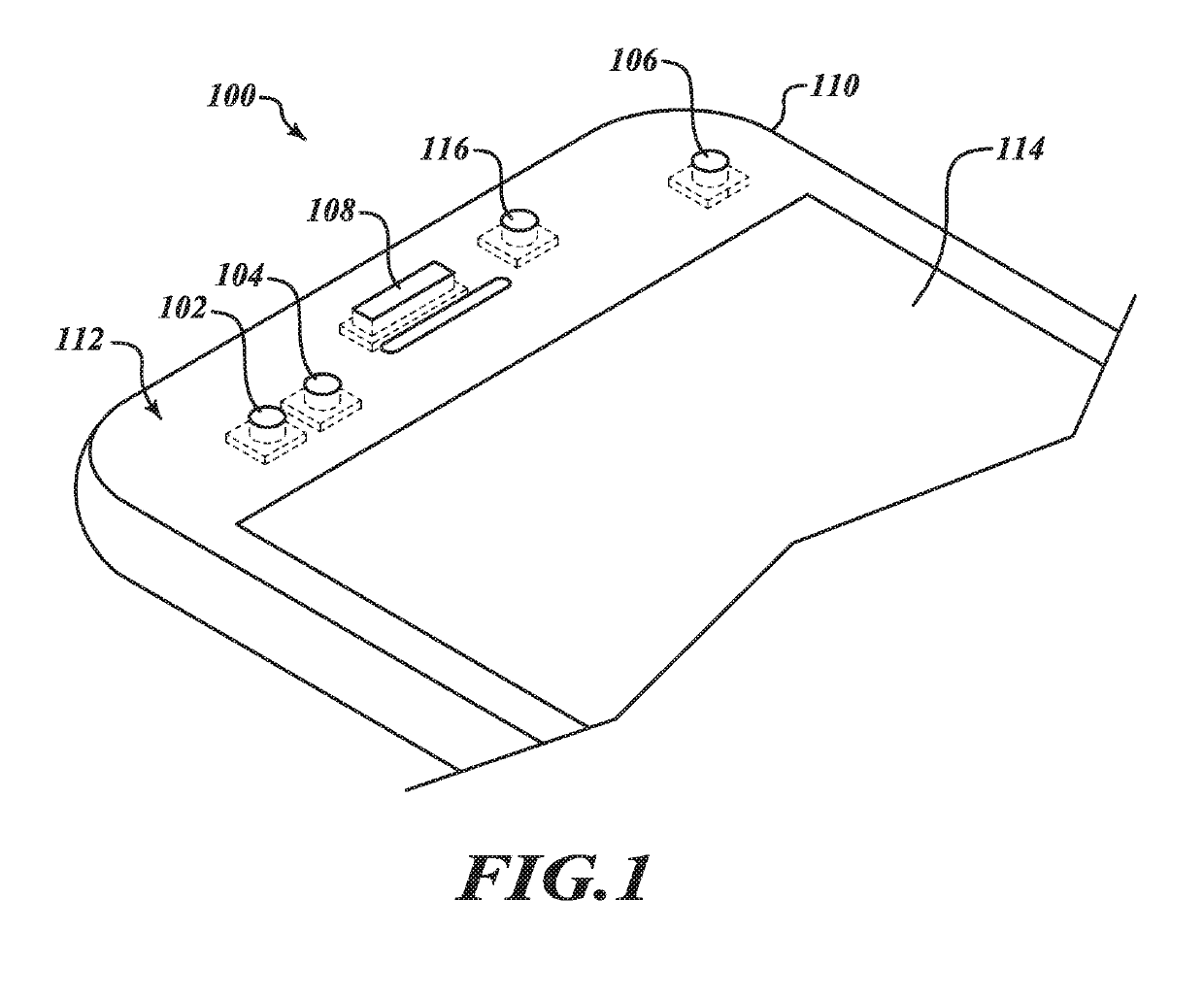
[0017]In the following description, certain specific details are set forth in order to provide a thorough understanding of various disclosed embodiments. However, one skilled in the relevant art will recognize that embodiments may be practiced without one or more of these specific details, or with other methods, components, materials, etc. In other instances, well-known algorithms associated with facial recognition, facial detection, and facial authentication have not been shown or described in detail, to avoid unnecessarily obscuring descriptions of the embodiments. Further, well-known structures associated with the time of flight sensor have not been shown or described in detail, to avoid unnecessarily obscuring descriptions of the embodiments.

[0018]Unless the context requires otherwise, throughout the specification and claims which follow, the word “comprise” and variations thereof, such as, “comprises” and “comprising” are to be construed in an open, inclusive sense, that is as ...


PUM


Abstract

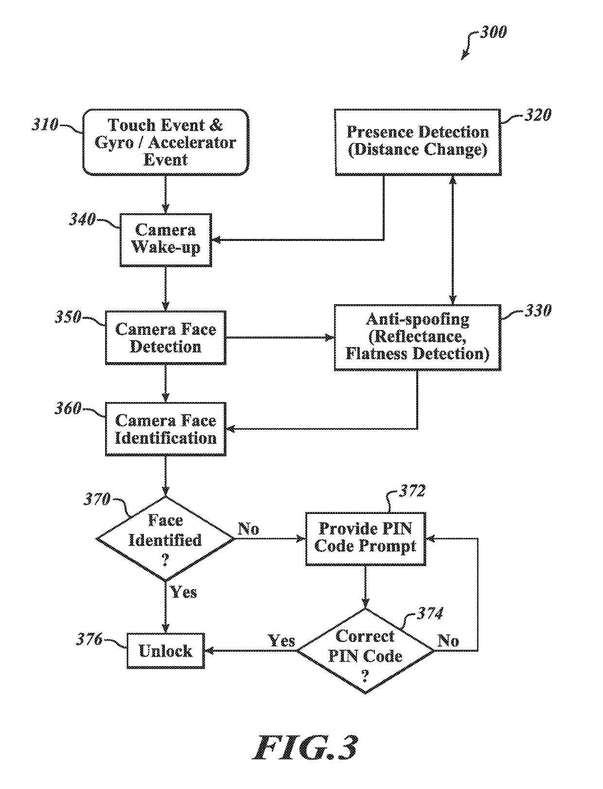
The present disclosure is directed to a system and method of authenticating a user's face with a ranging sensor. The ranging sensor includes a time of flight sensor and a reflectance sensor. The ranging sensor transmits a signal that is reflected off of a user and received back at the ranging sensor. The received signal can be used to determine distance between the user and the sensor, and the reflectance value of the user. With the distance or the reflectivity, a processor can activate a facial recognition process in response to the distance and the reflectivity. A device incorporating the ranging sensor according to the present disclosure may reduce the overall power consumed during the facial authentication process.

Description

BACKGROUNDTechnical Field[0001]The present application is directed to a facial authentication system that utilizes a time of flight sensor to identify a user's face for authentication purposes.Descriptions of the Related Art[0002]Conventional facial authentication systems use image sensors such as RGB cameras (i.e., cameras that capture red R, green G, blue B bands, so that the images the cameras produce recreate almost exactly what the human eyes see), infrared (IR) cameras, sensors using structured light, stereoscopic cameras or the like mounted on an electronic device to authenticate a user's face for granting access to use the electronic device. Some of the examples of conventional facial authentication systems include Apple's Face ID, Microsoft's Windows Hello, and Samsung Galaxy's face recognition system. Such facial authentication systems require a significant amount of image processing power in the device. and accordingly consume more power during the authentication process....

Claims


Application Information

Patent Timeline
IPC IPC(8): G06F21/32G06K9/00G01S17/02G01S17/08G01S17/89G06T7/521G01S7/486G06K9/20G01S7/4865G01S17/04G01S17/894G06V10/141
CPCG06F21/32G06K9/00288G06K9/00255G01S17/026G01S17/08G01S17/89G06T7/521G01S7/4865G06K9/2027G06T2207/30201G06T2207/10048G06T2207/10028G01S7/4808G01S7/4802G01S17/88G01S17/04G01S17/894G06V40/166G06V40/172G06V10/141
Inventor MORESTIN, FREDERICYANG, XIAOYONG
Owner STMICROELECTRONICS SRL
Learn More