System and a method for optimizing the trajectory to be followed when weeding crops

Active Publication Date: 2019-07-18
AGRO INTELLIGENCE APS
View PDF0 Cites 3 Cited by
  • Summary
  • Abstract
  • Description
  • Claims
  • Application Information

AI Technical Summary

Benefits of technology

[0019]It is an objective of the present invention to provide systems, uses and methods for improving efficiency when weeding distinct areas of weed within a crop field. Specifically it is an objective of t

Problems solved by technology

The disadvantages covering the entire field, and hence not following an optimum route through the crop field is that an overall inefficiency results.
This inefficiency may relate to excessive time spen

Method used


Image

  • System and a method for optimizing the trajectory to be followed when weeding crops
  • System and a method for optimizing the trajectory to be followed when weeding crops
  • System and a method for optimizing the trajectory to be followed when weeding crops

Examples


example 1

[0163]This example is intended for illustrating one way of mathematically processing a situation of having a boundary of a field having located there in a number of obstacles in order to create an array of possible working rows and headlands within that field which may be connected in various ways in order to create an array of possible continuous working paths to be followed.

[0164]In doing this an efficiency parameter may be assigned and calculated in respect of possible continuous working path and the most efficient continuous working path can be selected among the array of possible continuous working paths.

[0165]The principle set out in this example relies on the following steps:

[0166]1. Define the boundary of the field.

[0167]2. Define the boundary of any obstacle.

[0168]3. Approximate the boundary of the field to a boundary polygon.

[0169]4. Optionally approximate the boundary of any obstacle to an obstacle polygon.

[0170]5. Define one or more headlands arranged immediately within ...

example 2

[0319]This example illustrates the present invention. This example illustrates in an simplified and idealized way how the invention is to be conducted.

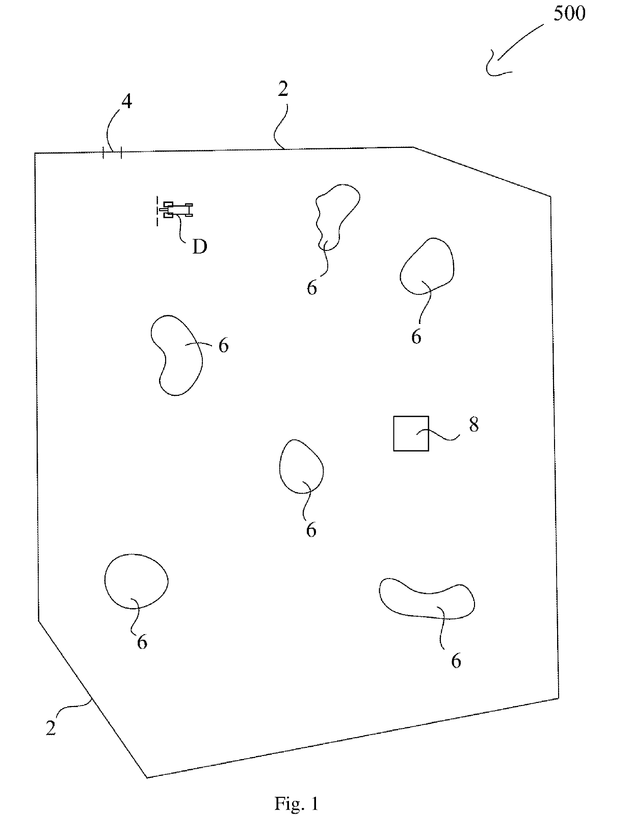
[0320]In this example a crop field comprising a number of distinct weed areas are defined. FIG. 24 illustrates the field to worked. The field 500 is constrained within a field boundary 2. At a specific location on the field boundary 2 an entrance / exit gate 4 is located.

[0321]The field boundary comprises two pairs of parallel lines. In the lower right corner in FIG. 24 two perpendicular boundary lines are connected by a circular path

[0322]Within the field boundary three distinct areas 6 of weed areas are present. Additionally an obstacle 8, which must be avoided when working the field, is located within the field boundary 2.

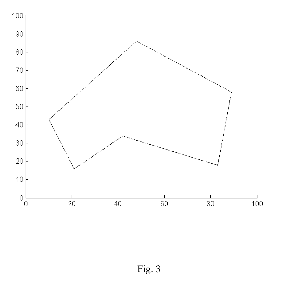
[0323]In this example of performing the method of the invention, first the field boundary is approximated to the shape of a polygon. This is illustrated in FIG. 25.

[0324]FIG. 25 shows that the boundary 2 of FIG. 24 ...


PUM


Abstract

The present invention relates to a support system for determining a trajectory to be followed by an agricultural work vehicle when weeding distinct areas of weed within a field of crops, said system comprises:
a mapping unit configured for receiving:
    • i) coordinates relating to the boundaries of a field to be worked; and
    • ii) coordinates relating to the boundaries of distinct areas of weed being located within said boundary of said field of crops;
a capacity parameter unit configured for receiving one or more capacity parameters relating to said working vehicle;
a trajectory calculating unit configured for calculating an optimized trajectory to be followed by said work vehicle upon weeding said distinct areas of weed; wherein said optimized trajectory is being calculated on the basis of said coordinates received by said mapping unit; and one or more of said one or more capacity parameters received by said capacity parameter unit.

Description

FIELD OF THE INVENTION[0001]The present invention generally relates to the field of optimizing work trajectories of agricultural working vehicles for working a field.[0002]More specifically the present invention relates in a first aspect to a support system for determining a trajectory to be followed by an agricultural work vehicle when weeding distinct areas of weed in a crop field.[0003]In a second aspect the present invention relates to a method for optimizing a trajectory to be followed by an agricultural work vehicle when weeding distinct areas of weed in a crop field.[0004]In a third aspect the present invention relates to a computer program product, which when being loaded or operating on a computer, being adapted to perform the method according to the second aspect.[0005]In a fourth aspect the present invention relates to an agricultural work vehicle comprising a weeding implement as well as a support system according to the first aspect.[0006]In a fifth aspect the present i...

Claims


Application Information

Patent Timeline
IPC IPC(8): A01B79/00G01C21/00
CPCA01B79/005G01C21/00A01B69/008G05D1/0219G05D1/0217G05D2201/0201
Inventor GREEN, OLEEDWARDS, GARETH THOMAS CHARLES
Owner AGRO INTELLIGENCE APS
Why Eureka
Try Eureka