
Vehicle lamp using semiconductor light emitting device

Active Publication Date: 2019-07-18
LG ELECTRONICS INC
View PDF8 Cites 0 Cited by
  • Summary
  • Abstract
  • Description
  • Claims
  • Application Information

AI Technical Summary

Benefits of technology

The present invention is a vehicle lamp that reduces the optical loss of a semiconductor light emitting device. It achieves this by stacking components in a specific order, using a reflective film, an insulating layer, and a wiring. An exposure groove is also formed in the insulating layer to improve reflection efficiency and increase the brightness of the light source. The insulating layer has a structure that increases brightness by opening the lateral direction of the semiconductor light emitting device. Additionally, a light extraction pattern is provided on the light-transmitting connection electrode to reduce light absorption by the metal wiring.

Problems solved by technology

Vehicle lamps ever developed use LEDs in a package form and thereby have disadvantages, such as a low mass production yield rate, high fabrication costs and low flexibility.
However, brightness may be lowered due to an optical loss of the semiconductor light emitting devices.
This results in reducing overall uniformity of a light source, and thus a structure that can solve this problem is also needed.

Method used


Image

  • Vehicle lamp using semiconductor light emitting device
  • Vehicle lamp using semiconductor light emitting device
  • Vehicle lamp using semiconductor light emitting device

Examples


Embodiment Construction

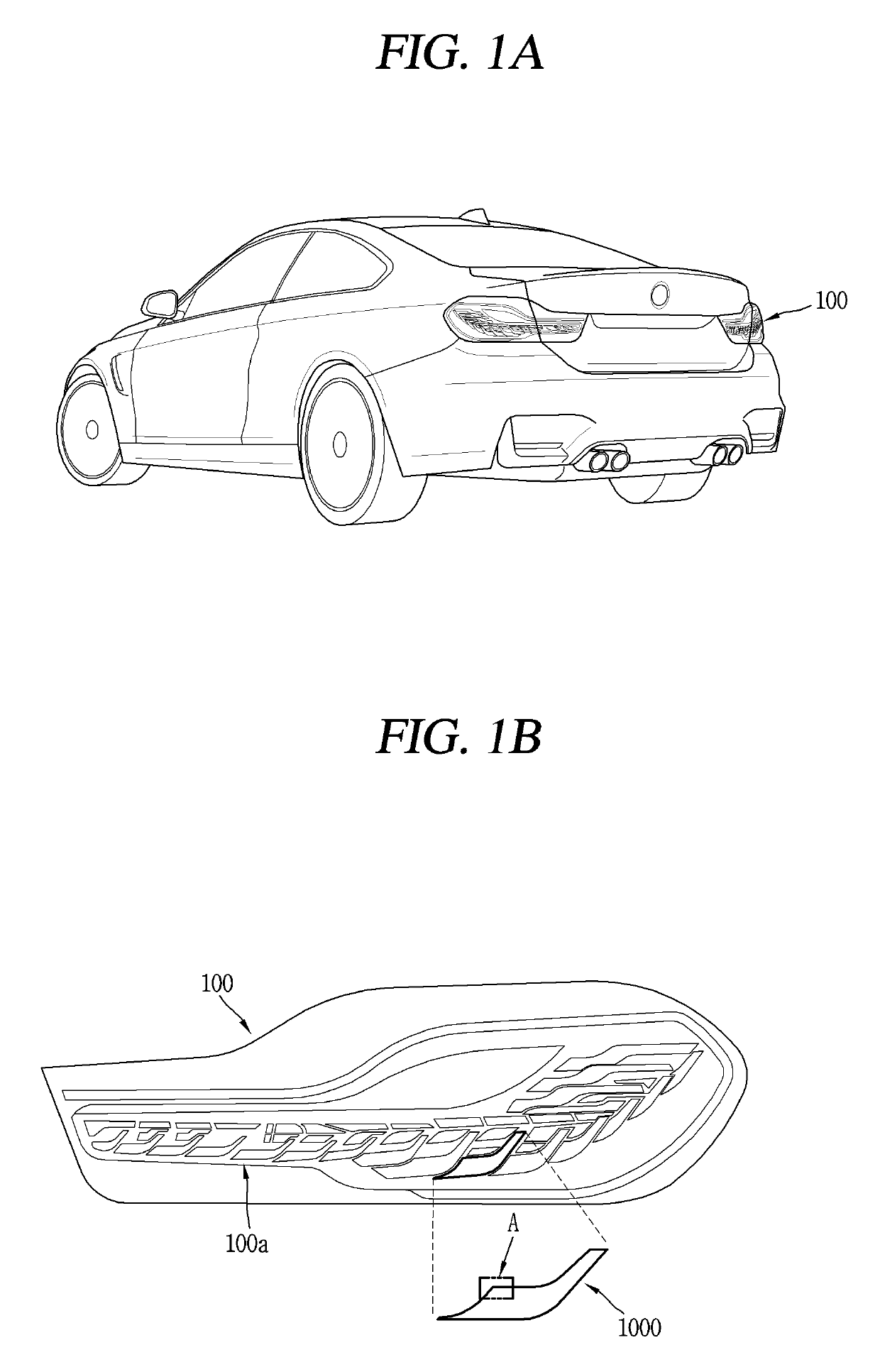
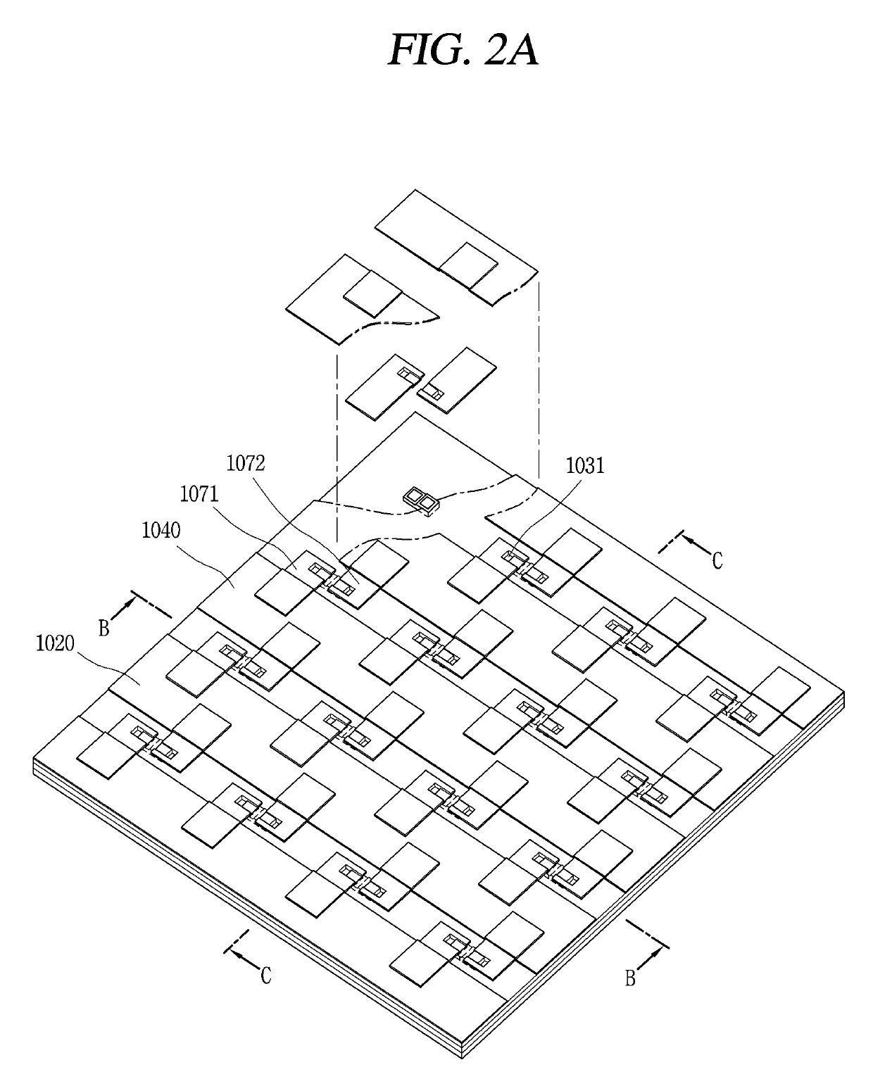
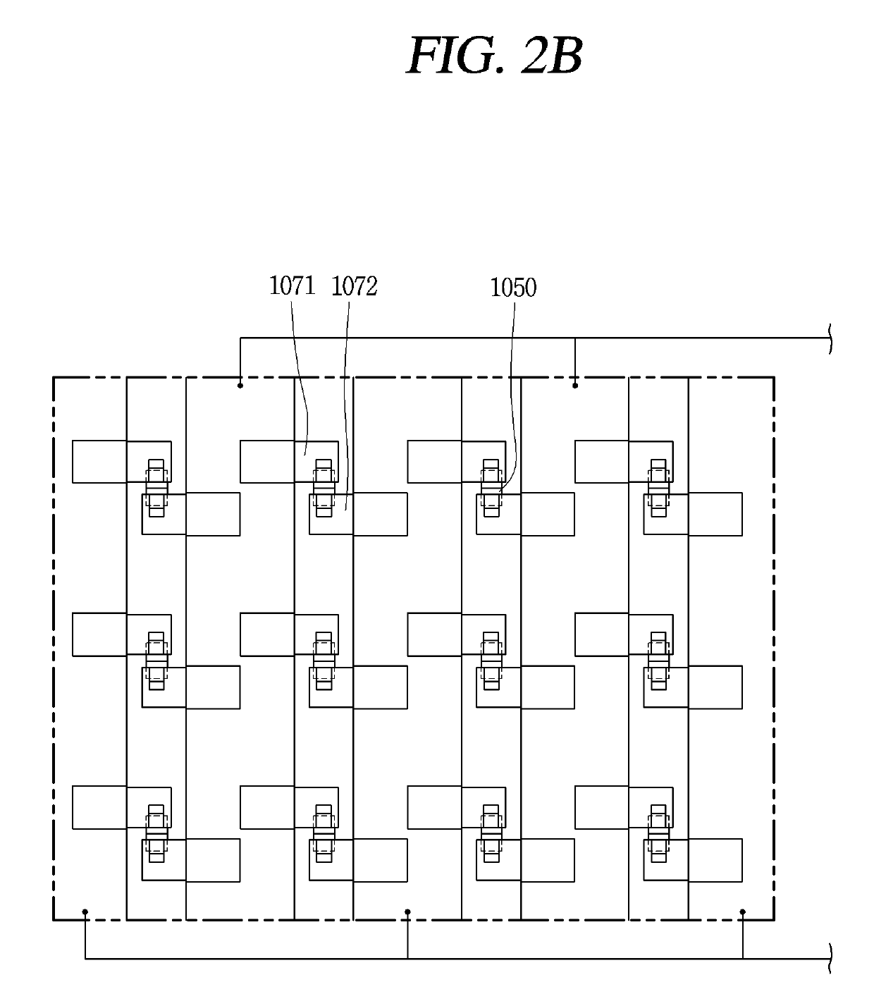
[0036]Description will now be given in detail according to exemplary embodiments disclosed herein, with reference to the accompanying drawings. For the sake of brief description with reference to the drawings, the same or equivalent components may be provided with the same or similar reference numbers, and description thereof will not be repeated. In general, a suffix such as “module” and “unit” may be used to refer to elements or components. Use of such a suffix herein is merely intended to facilitate description of the specification, and the suffix itself is not intended to give any special meaning or function. In describing the present disclosure, if a detailed explanation for a related known function or construction is considered to unnecessarily divert the gist of the present disclosure, such explanation has been omitted but would be understood by those skilled in the art. The accompanying drawings are used to help easily understand the technical idea of the present disclosure ...


PUM


Abstract

The present invention relates to a vehicle lamp using a semiconductor light emitting device, and the vehicle lamp includes a light source unit to emit light. The light source unit includes a substrate having a reflective film, a semiconductor light emitting device coupled to the substrate, an insulating layer stacked on the reflective film to surround the semiconductor light emitting device, a first electrode and a second electrode disposed on an upper surface of the insulating layer, and light-transmitting connection electrodes extending from the first and second electrodes, respectively, electrically connected to the semiconductor light-emitting device, and covering an upper surface of the semiconductor light-emitting device.

Description

CROSS-REFERENCE TO RELATED APPLICATION[0001]Pursuant to 35 U.S.C. § 119(a), this application claims the benefit of earlier filing date and right of priority to Korean Application No. 10-2018-0005732, filed on Jan. 16, 2018, the contents of which is incorporated by reference herein in its entirety.BACKGROUND OF THE INVENTION1. Field of the Invention[0002]The present invention relates to a vehicle lamp (or car lamp), and more particularly, a vehicle lamp using a semiconductor light emitting device.2. Description of the Related Art[0003]A vehicle is equipped with various lamps having lighting functions and signaling functions. In general, halogen lamps or gas discharge lamps are usually used, but in recent years, light emitting diodes (LEDs) are in the spotlight as light sources for vehicle lamps.[0004]The LED can enhance a degree of freedom for design of a lamp by minimizing a size thereof and exhibit economic efficiency by virtue of a semi-permanent lifespan, but most of the LEDs are...

Claims


Application Information

Patent Timeline
IPC IPC(8): F21S43/14H01L33/10H01L33/36H01L33/62
CPCF21S43/14H01L33/10H01L33/36H01L33/62F21Y2115/10H01L25/0753H01L33/44H01L33/60F21S43/15F21S43/195H01L33/38F21S2/005
Inventor LEE, SUNGWHANSONG, HOOYOUNGLEE, KYUNGHO
Owner LG ELECTRONICS INC
Learn More