Airflow sensor

a sensor and airflow technology, applied in the field of airflow sensors, can solve the problems of spring index, inability to accurately sense airflow, and inability to accurately control the air-fuel ratio of the boiler, so as to improve the reliability of airflow sensing, reduce the defect rate, and improve the structure

Inactive Publication Date: 2019-07-18
KYUNGDONG NAVIEN
View PDF0 Cites 1 Cited by
  • Summary
  • Abstract
  • Description
  • Claims
  • Application Information

AI Technical Summary

Benefits of technology

[0009]The present disclosure is directed to providing an airflow sensor configured to reduce a defect rate even during long-term use and improve reliability of airflow sensing so that a boiler is controlled at an accurate air-fuel ratio by improving a structure of an elastic member which is a critical component thereof.

Problems solved by technology

However, since a free field (see FIG. 1) dimension defect due to instability of a spring index (a value in which a center diameter is divided by a diameter in FIG. 1) occurs when the airflow sensor, in which the coil spring is mounted, is used for a long time, airflow cannot be accurately sensed, and accordingly, an air-fuel ratio of the boiler cannot be accurately controlled.
The instability of the spring index and the free field dimension defect of the coil spring are caused due to a structural characteristic of the coil spring having weak tensile strength and yield strength and thus causing plastic deformation when used for a long time.

Method used


Image

  • Airflow sensor
  • Airflow sensor
  • Airflow sensor

Examples


Embodiment Construction

[0032]Hereinafter, a configuration and an action of an embodiment of the present disclosure will be described in detail with reference to the accompanying drawings.

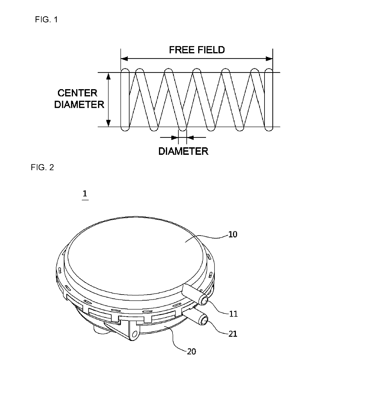
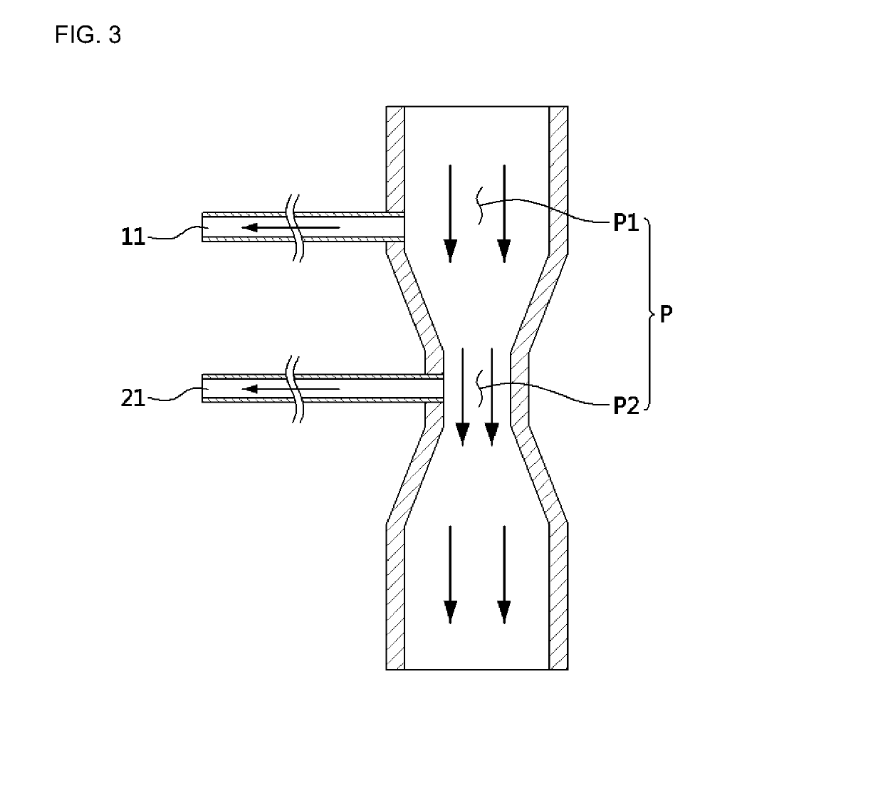
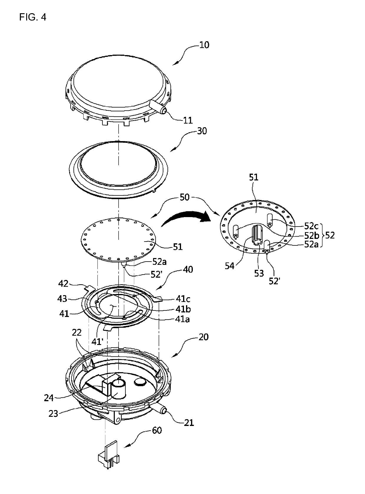
[0033]Referring to FIGS. 2 to 4, an airflow sensor 1 of the present disclosure includes cases 10 and 20 respectively having a first air introduction port 11 connected to one side flow path P1 of a flow path P in which a differential pressure is formed and a second air introduction port 21 connected to the other side flow path P2 formed therein, a diaphragm 30 configured to partition the insides of the cases 10 and 20 into a first space S1 connected to the first air introduction port and a second space S2 connected to the second air introduction port 21 and displaced according to pressure variation of the first space S1 (see FIG. 9(a) and FIG. 9(b)) and the second space S2, an elastic member 40 formed of a plate spring having an elastic force which acts so that the diaphragm 30 is restored to a location before being displa...


PUM

PropertyMeasurementUnit
differential pressureaaaaaaaaaa
pressureaaaaaaaaaa
elastic forceaaaaaaaaaa

Abstract

The present disclosure is directed to providing an airflow sensor having an improved structure of an elastic member which is a critical component thereof to reduce a defect rate even during long-term use and improve reliability of airflow sensing so that a boiler is controlled at an accurate air-fuel ratio.
The airflow sensor of the present disclosure includes a case having a first air introduction port connected to one side of a flow path in which a differential pressure is formed and a second air introduction port connected to the other side of the flow path formed therein, a diaphragm configured to partition the inside of the case into a first space connected to the first air introduction port and a second space connected to the second air introduction port and displaced according to pressure variation of the first space and the second space, an elastic member formed of a plate spring having an elastic force which acts so that the diaphragm is restored to a location before being displaced, an elevation member displaced along with the diaphragm, and a sensing member configured to sense a displacement amount of the elevation member.

Description

CROSS-REFERENCE TO RELATED APPLICATION[0001]This application claims priority to and the benefit of Korean Patent Application No. 10-2018-0005356, filed on Jan. 16, 2018, the disclosure of which is incorporated herein by reference in its entirety.BACKGROUND1. Field of the Invention[0002]The present disclosure relates to an airflow sensor configured to sense whether overpressure occurs or a headwind flows in a boiler flue, and more specifically, to an airflow sensor configured to reduce a defect rate even during long-term use and improve the reliability of airflow sensing so that a boiler is controlled at an accurate air-fuel ratio by improving a structure of an elastic member which is a critical component thereof.2. Discussion of Related Art[0003]Generally, in an apparatus configured to mix air and fuel to combust the fuel, such as a boiler, combustion efficiency is determined according to how accurately a mixture ratio of the air and the fuel is controlled. Accordingly, in order to ...

Claims


Application Information

Patent Timeline
Patent Type & Authority Applications(United States)
IPC IPC(8): G01L13/02G01L13/06
CPCG01L13/025G01L13/06G01F3/22G01F15/16G01F15/14
Inventor CHOO, GYO YOUNGYANG, HYUN IK
Owner KYUNGDONG NAVIEN
Why Eureka
Try Eureka