Eureka AIR delivers breakthrough ideas for toughest innovation challenges, trusted by R&D personnel around the world.

Optical element for a lidar system

Active Publication Date: 2019-07-18
ROBERT BOSCH GMBH
View PDF0 Cites 3 Cited by
  • Summary
  • Abstract
  • Description
  • Claims
  • Application Information

AI Technical Summary

Benefits of technology

The invention describes an improved optical element for a lidar system. The optical element uses a holographic optical element to create a larger optical system and / or a projection lens for the lidar system. This holographic optical element helps to increase the amount of photons collected and ensures better eye safety and robustness. The method for producing this optical element involves creating a hologram of the desired optical system and then using it to create the actual optical element. This approach allows for easier and more precise production of the optical element. Overall, the invention provides a more effective and safer optical element for lidar systems.

Problems solved by technology

However, the small mirror diameter can have disadvantageous effects with regard to eye safety and robustness.
In addition, it is possible only with difficulty to make these micro mirror-based systems coaxial, i.e. having an identical optical path for the transmit and receive path, because the micromirror limits the receive aperture too greatly, and as a result not enough photons can be collected.

Method used


Image

  • Optical element for a lidar system
  • Optical element for a lidar system
  • Optical element for a lidar system

Examples


Embodiment Construction

[0036]An important aspect of the present invention is to provide at least one holographic optical system for a coaxial lidar system in which a common optical path is provided for the transmit and receive path. In this way, limitations of conventional optical systems can be overcome, and the constructive space of the overall system can be reduced, or angles of deflection of the scanning laser beams can be increased.

[0037]For this purpose, holographic materials based on polymer materials may be used that act as diffraction gratings in the infrared spectral range. The named polymer materials have advantageous properties for use in the automotive field, because they are very resistant to the environmental influences that prevail there (e.g. fluctuations of temperature or of humidity, etc.).

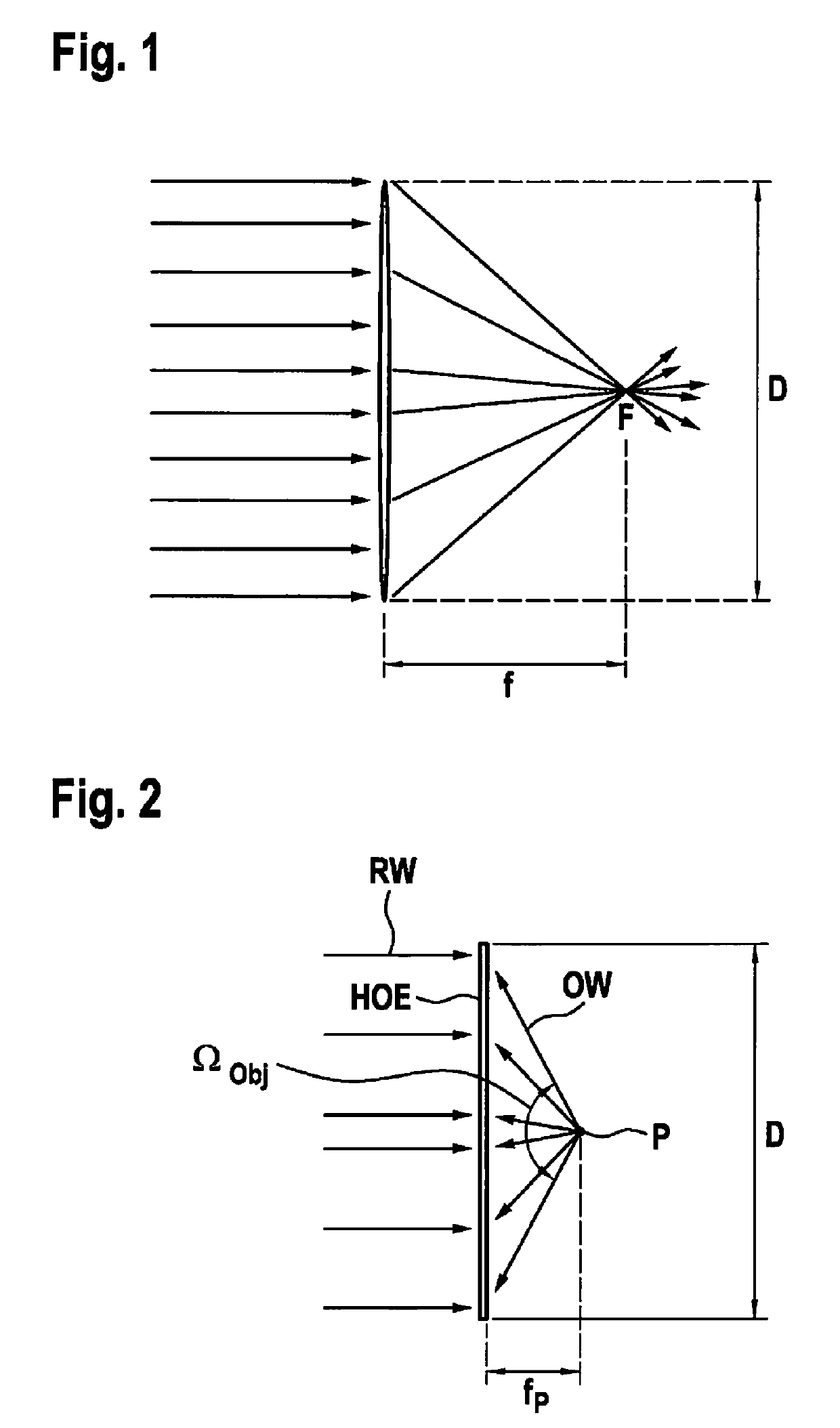
[0038]FIG. 1 shows the configuration of a conventional optical system having a lens having a diameter D, a focal length f, and a focal point F. Here the following mathematical equation or condition ho...


PUM


Abstract

An optical element for a lidar system, having: an expanding optical system and a projection lens, the expanding optical system and / or the projection lens being formed by a holographic optical element.

Description

FIELD OF THE INVENTION[0001]The present invention relates to an optical element for a lidar system. The present invention also relates to a method for producing an optical element for a lidar system.BACKGROUND INFORMATION[0002]In the existing art, there are lidar sensors, for example in the automotive field in the form of so-called TOF (time of flight) sensors that conduct transmitted light to the surrounding environment via a deflecting mirror or a transmission optical system, and acquire reflected radiation. There are various technical configurations of such lidar sensors. On the one hand, so-called macroscanners are used, in which a, for example, rotating macromirror has a diameter in the centimeter range. In this way, in the transmission path a beam having a diameter in the centimeter range can be guided via the rotating macromirror. The large beam diameter has advantages with regard to maintaining eye safety, because the diameter of a human pupil, assumed to be 7 mm in relevant...

Claims


Application Information

Patent Timeline
IPC IPC(8): G01S7/481G02B5/32
CPCG01S7/4817G01S7/4812G02B5/32G01S7/4814G01S7/4818G03H2001/0439
Inventor FREDERIKSEN, ANNETTEHARTMANN, STEFANIE
Owner ROBERT BOSCH GMBH
Why Eureka
Eureka Blog
Learn More