Communication system

a communication system and communication system technology, applied in the field of communication systems, can solve problems such as collision risks, and achieve the effects of suppressing the transmission rate and efficiently using radio resources

Active Publication Date: 2019-07-18
MITSUBISHI ELECTRIC CORP
View PDF3 Cites 22 Cited by
  • Summary
  • Abstract
  • Description
  • Claims
  • Application Information

AI Technical Summary

Benefits of technology

[0066]In a communication system according to the present invention, a base station device communicates with a communication terminal device using a self-contained subframe including a downlink signal and an uplink signal. The base station device notifies the communication terminal device of a structure of the uplink signal. This enables the communication terminal device to recognize the structure of the uplink signal in the self-contained subframe. Thus, the communication terminal device can transmit the uplink signal using the self-contained subframe.
[0067]Since the uplink signal includes an uplink control signal, and uplink user data to be transmitted before and after the uplink control signal, a gap duration between the downlink signal and the uplink signal during which the uplink signal and the downlink signal are not transmitted can be reduced. The retransmission of the downlink signal in the next self-contained subframe can be performed with the gap duration after transmitting the uplink signal eliminated or reduced. Consequently, the radio resources can be efficiently used. Thus, decrease in the transmission rate with the self-contained subframe can be suppressed.
[0068]These and other objects, features, aspects and advantages of the present invention will become more apparent from the following detailed description of the present invention when taken in conjunction with the accompanying drawings.

Problems solved by technology

The RACH involves a collision risk.

Method used


Image

  • Communication system
  • Communication system
  • Communication system

Examples


first embodiment

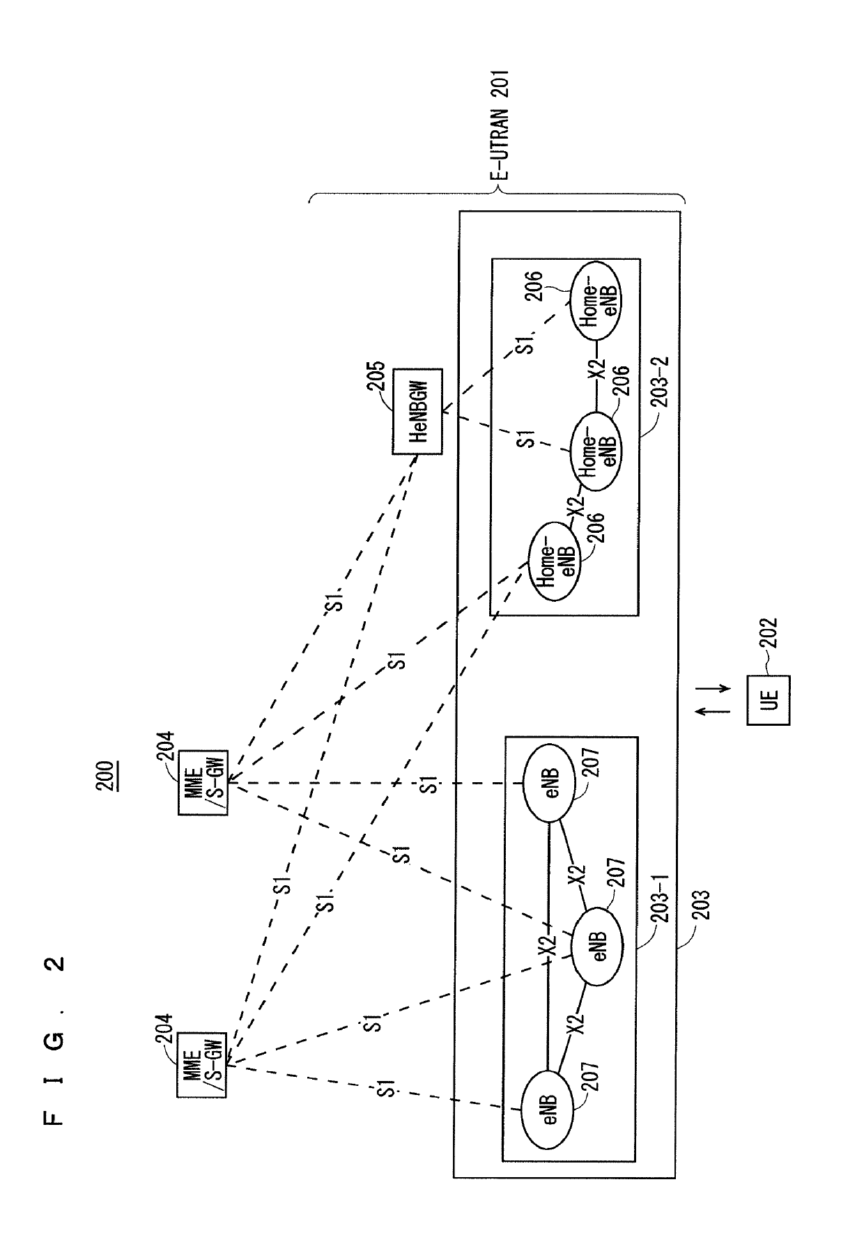
[0133]FIG. 2 is a block diagram showing an overall configuration of an LTE communication system 200, which is under discussion of 3GPP. FIG. 2 will be described. A radio access network is referred to as an evolved universal terrestrial radio access network (E-UTRAN) 201. A user equipment device (hereinafter, referred to as a “user equipment (UE)”) 202 that is a communication terminal device is capable of radio communication with a base station device (hereinafter, referred to as a “base station (E-UTRAN Node B: eNB)”) 203 and transmits and receives signals through radio communication.

[0134]Here, the “communication terminal device” covers not only a user equipment device such as a movable mobile phone terminal device, but also an unmovable device such as a sensor. In the following description, the “communication terminal device” may be simply referred to as a “communication terminal”.

[0135]The E-UTRAN is composed of one or a plurality of base stations 203, provided that a control pro...

fourth modification

of First Embodiment

[0400]The fourth modification will describe a scheduling method to enable retransmission in a subframe next to a subframe in which Ack / Nack has been received, without using, in the self-contained subframe, the downlink control information on the subframe in retransmission.

[0401]Although the eNB transmits the downlink control information to the UE also in its retransmission in the methods according to the second and third modifications of the first embodiment, the eNB performs scheduling without transmitting the downlink control information to the UE in the retransmission according to the fourth modification.

[0402]The eNB allocates, to the retransmission, the same frequency resources and the same modulating method as those for the initial transmission. In the retransmission, the redundancy version (RV) may be changed from that for the initial transmission. Consequently, the error correction capability in the retransmission can be increased.

[0403]The eNB and the UE ...

fifth modification

of First Embodiment

[0420]The fifth modification will describe another specific example of the scheduling method to enable retransmission in a subframe next to a subframe in which Ack / Nack has been received, without using, in the self-contained subframe, the downlink control information on the subframe in retransmission.

[0421]The fourth modification of the first embodiment poses a problem where radio resources that are the same as those for the initial transmission data sometimes cannot be used depending on a subframe, for example, a subframe in which a synchronization signal and a physical broadcast information channel are transmitted.

[0422]The fifth modification will disclose a method for solving such a problem.

[0423]In the scheduling for initial transmission, scheduling for the k retransmissions is performed. Here, k may be an integer ranging from 1 to the maximum number of retransmissions. k may not be the value indicating the maximum number of retransmissions. The retransmission...


PUM


Abstract

Provided is a communication system capable of suppressing decrease in a transmission rate. An eNB communicates with a UE using a self-contained subframe. The self-contained subframe includes a downlink signal to be transmitted from the eNB to the UE, and an uplink signal to be transmitted from the UE to the eNB in response to the downlink signal. The uplink signal has a structure including an uplink control signal indicating information for controlling transmission of the uplink signal, and uplink user data to be transmitted before and after the uplink control signal. The eNB notifies the UE of a structure of the uplink signal.

Description

TECHNICAL FIELD[0001]The present invention relates to a communication system in which radio communication is performed between a communication terminal device such as a user equipment device and a base station device.BACKGROUND ART[0002]The 3rd generation partnership project (3GPP), the standard organization regarding the mobile communication system, is studying communication systems referred to as long term evolution (LTE) regarding radio sections and system architecture evolution (SAE) regarding the overall system configuration including a core network and a radio access network, which will be hereinafter collectively referred to as a network as well (for example, see Non-Patent Documents 1 to 5). This communication system is also referred to as 3.9 generation (3.9 G) system.[0003]As the access scheme of the LTE, orthogonal frequency division multiplexing (OFDM) is used in a downlink direction and single carrier frequency division multiple access (SC-FDMA) is used in an uplink dir...

Claims


Application Information

Patent Timeline
Patent Type & Authority Applications(United States)
IPC IPC(8): H04L1/18H04W72/04H04L25/02H04L5/00H04W24/10H04W74/08H04W76/27H04W48/10H04W80/02
CPCH04L1/1819H04L1/189H04W72/0446H04L25/0226H04L5/005H04L5/0055H04W24/10H04W74/0833H04W76/27H04W48/10H04W80/02H04W28/04H04W28/06H04L5/0082H04L1/0006H04L1/0023H04W72/04H04L1/1887H04L1/1896H04L5/0035H04L5/0048H04L5/0053H04L5/0007H04W72/0453H04W72/21H04W72/23
Inventor SHIMODA, TADAHIROMOCHIZUKI, MITSURUNAKAZAWA, MASAYUKIHASEGAWA, FUMIHIRO
Owner MITSUBISHI ELECTRIC CORP
Why Eureka
Try Eureka