Driving tool

a technology of driving tool and ignition performance, which is applied in the direction of manufacturing tools, machines/engines, non-mechanical valves, etc., can solve the problems of deteriorating output of next driving or ignition performance of the mixture in the combustion chamber, so as to avoid driving in an unstable state, prevent the return failure of the piston, and stabilize the driving operation

Inactive Publication Date: 2019-07-25
MAX CO LTD
View PDF6 Cites 3 Cited by
  • Summary
  • Abstract
  • Description
  • Claims
  • Application Information

AI Technical Summary

Benefits of technology

[0020]According to the invention, the scavenging in the combustion chamber is performed after the driving operation is completed. Thus, it is possible to prevent the return failure of the piston and to stabilize the driving operation.
[0021]According to the invention, the operation of the mechanism part is stopped in a case where the abnormality of the mechanism part of the driving tool is detected. Thus, it is possible to avoid the driving in an unstable state. Accordingly, it is possible to stabilize the driving operation.
[0022]The invention is as described above, and the output part and the grip are connected with a gap to be movable to each other. Thus, the output part and the grip move relatively when the output part is operated. Further, since the elastic member is arranged in the gap, the elastic member can receive the impact generated when the output part and the grip move relatively. Therefore, the impact vibration applied to the grip can be prevented with a simple structure. By preventing the impact vibration applied to the grip, the burden applied to the operator can be reduced, and the malfunction or the breakage of the switch provided in the grip can be prevented.
[0023]Since the impact vibration applied to the grip can be prevented, the grip can be configured by a lightweight material such as plastic. Therefore, the driving tool is reduced in weight to become easy to handle.

Problems solved by technology

When the next driving operation is performed in a state where the exhaust gas remains in the combustion chamber, there is a problem such that the output of the next driving or the ignition performance of the mixture in the combustion chamber is deteriorated.

Method used


Image

  • Driving tool
  • Driving tool
  • Driving tool

Examples


first embodiment

[0051][Configuration Example of Driving Tool 10]

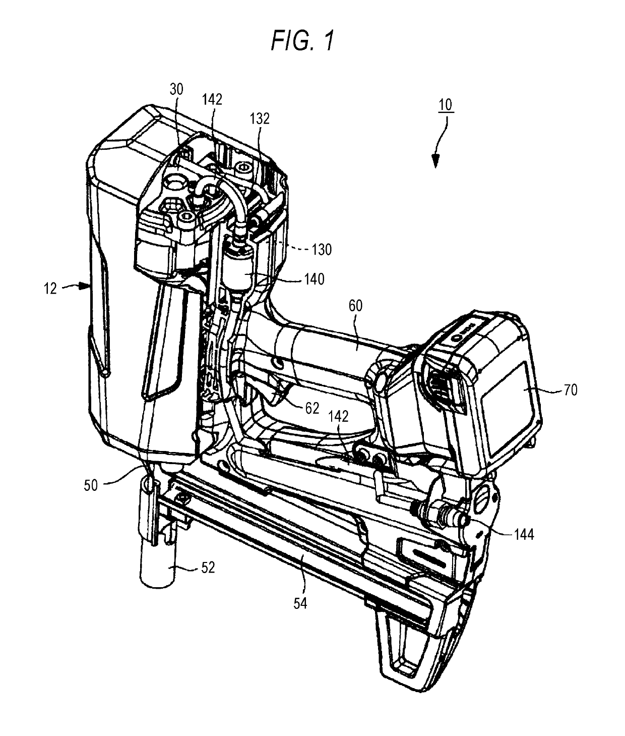
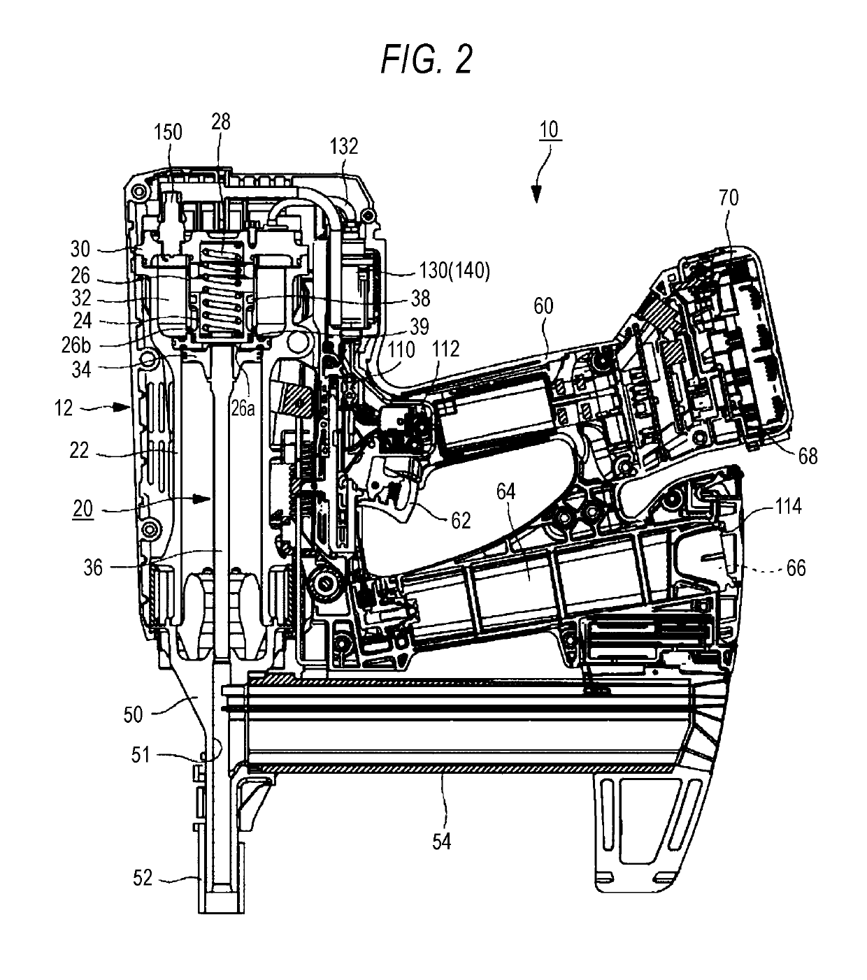
[0052]FIGS. 1 and 2 illustrate one example of a configuration of the driving tool 10 according to one embodiment of the invention in FIGS. 1 and 2, a nail driving direction is set to a lower side, and the opposite side thereof is set to an upper side. In FIGS. 1 and 2, a tool body 12 is set to a front side, a the battery 70 is set to a rear side, a contact arm 52 is set to a lower side, and a cylinder head 30 is set to an upper side. In the direction orthogonal to the longitudinal direction and the vertical direction of the driving tool 10, when the front direction is set as a reference, the right side is set to the right side of the driving tool 10, and the left side is set to the left side of the driving tool 10.

[0053]As illustrated in FIGS. 1 and 2, the driving tool 10 is a tool which drives a fastener such as a nail, a staple, and a pin into a driving target member such as wood, gypsum board, steel plate, and concrete. The driving ...

second embodiment

[0134]In a second embodiment, the scavenging of the driving tool 10 will be described in detail. Incidentally, the basic configuration and operation of the driving tool 10 are similar to those of the first embodiment. Thus, the same reference numeral is attached to the common component, and the detailed description is omitted.

[0135][Timing Chart during Operation of Driving Tool 10]

[0136]FIG. 8 illustrates a timing chart of each device during the driving operation of the driving tool 10 according to the invention and a graph of a fluctuation of the pressure in the combustion chamber 32. Incidentally, in the graph, the vertical axis is pressure, and the horizontal axis is time.

[0137]As illustrated in FIG. 8, at time t1, when the contact arm 52 is pressed against the driving target member by the operator, the contact arm 52 moves relatively upward with respect to the nose 50, and when the contact switch 110 is switched from the high level to the low level, the contact switch 110 is tur...

first modification

of Second Embodiment

[0159]FIG. 9 is a flowchart illustrating one example of the scavenging operation in a case where the fuel container is mounted first, and then air source is mounted next.

[0160]As illustrated in FIG. 9, in step S200, the control unit 100 determines based on the output of the fuel container detection switch 114 whether or not the fuel container 66 is mounted in the gas cartridge storage part 64. In a case where it is determined that the fuel container 66 is not mounted in the gas cartridge storage part 64, the control unit 100 continuously monitors whether the fuel container 66 is mounted in the gas cartridge storage part 64. On the other hand, in a case where it is determined that the fuel container 66 is mounted in the gas cartridge storage part 64, the control unit 100 proceeds to step S210.

[0161]In step S210, the control unit 100 discharges the air previously accumulated in the fuel hose 132 or in the fuel injection valve 130 into the combustion chamber 32 by c...


PUM


Abstract

A driving tool includes a combustion chamber, a cylinder, a valve and a control unit. Fuel and compressed air are supplied into the combustion chamber. The cylinder is configured to movably store a piston which is driven by combustion pressure at a time of igniting a mixture of the fuel and the compressed air filled in the combustion chamber. The valve is configured to open and close a passage through which the compressed air is supplied into the combustion chamber. The control unit is configured to control the valve to supply the compressed air into the combustion chamber when the control unit determines that a return of the piston is completed.

Description

CROSS-REFERENCE TO RELATED APPLICATIONS[0001]This application is based on and claims priority under 35 USC 119 from Japanese Patent Application Nos. 2018-022480 filed on Feb. 9, 2018, 2018-022481 filed on Feb. 9, 2018, 2018-022482 filed on Feb. 9, 2018, and 2018-026624 filed on Feb. 19, 2018, 2018-007520 filed on Jan. 19, 2018, 2018-007521 filed on Jan. 19, 2018, and 2018-007633 filed on Jan. 19, 2018, the contents of which are incorporated herein by reference.TECHNICAL FIELD[0002]The invention relates to a driving tool. In addition, the invention relates to a driving tool which drives a fastener.[0003]In the related art, a driving tool which uses a ire of fuel and air comes into wide use. This kind of driving tool is configured such that after the mixture of the fuel and the air is generated in a combustion chamber, the mixture is ignited and combusted to generate high combustion pressure and drive a piston in a cylinder, and a nail supplied to a nose is struck by a driver integral...

Claims


Application Information

Patent Timeline
Patent Type & Authority Applications(United States)
IPC IPC(8): B25C1/08B25D9/10F02B63/02
CPCB25C1/08B25D9/10F02B63/02F01L9/02B25C1/14B25C1/18B25C1/008F01L9/10
Inventor YAMAMOTO, YUYUKI, TAKASHIKIMURA, MITSUHIROTAKAHASHI, YASUNORIKURITA, SHUHEIWATANABE, EIICHI
Owner MAX CO LTD
Why Eureka
Try Eureka