Display device and electronic apparatus

a technology of electronic equipment and display device, which is applied in the direction of static indicating equipment, instruments, etc., can solve the problems of increasing power consumption, difficult to correct the brightness between the display regions, and increasing the circuit scale of the driving circuit for driving the pixel circuit, so as to reduce power consumption, simplify the configuration of the driving circuit, and suppress the effect of the increase in the circuit scale of the driving circui

Inactive Publication Date: 2019-07-25
SEIKO EPSON CORP
View PDF2 Cites 4 Cited by
  • Summary
  • Abstract
  • Description
  • Claims
  • Application Information

AI Technical Summary

Benefits of technology

[0006]According to this aspect, for the second data transfer line and the third data transfer line that are applied with the same gradation signal, since only one output unit of the gradation signal has to be disposed in the driving circuit, as compared with an aspect in which the output units are disposed for each of all the data transfer lines, the configuration of the driving circuit is simplified, and power consumption can be reduced while an increase in the circuit scale of the driving circuit is suppressed.
[0007]The pixel circuit to which the same gradation signal is supplied via the second data transfer line and the third data transfer line display the same gradation, thus the resolution decreases. On the other hand, another gradation signal is applied to the first data transfer line, thus the resolution in a scanning line direction, that is, a horizon

Problems solved by technology

However, there is a problem that, when the number of the pixel circuits arranged in the display panel is increased, the circuit scale of the driving circuit for driving the pixel circuits is increased according to the increment of the number of pixel circuits.
Fu

Method used


Image

  • Display device and electronic apparatus
  • Display device and electronic apparatus
  • Display device and electronic apparatus

Examples


first exemplary embodiment

A. First Exemplary Embodiment

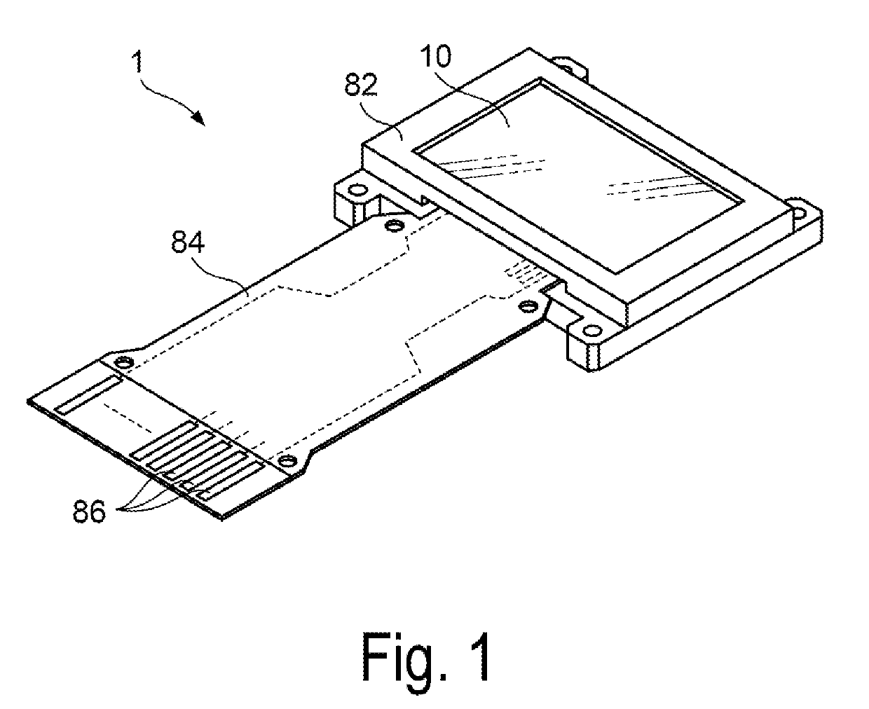
[0040]FIG. 1 is a perspective view illustrating a configuration of a display device 1 according to an exemplary embodiment of the invention. A display device 1 is, for example, a micro display that displays an image on a head-mounted display.

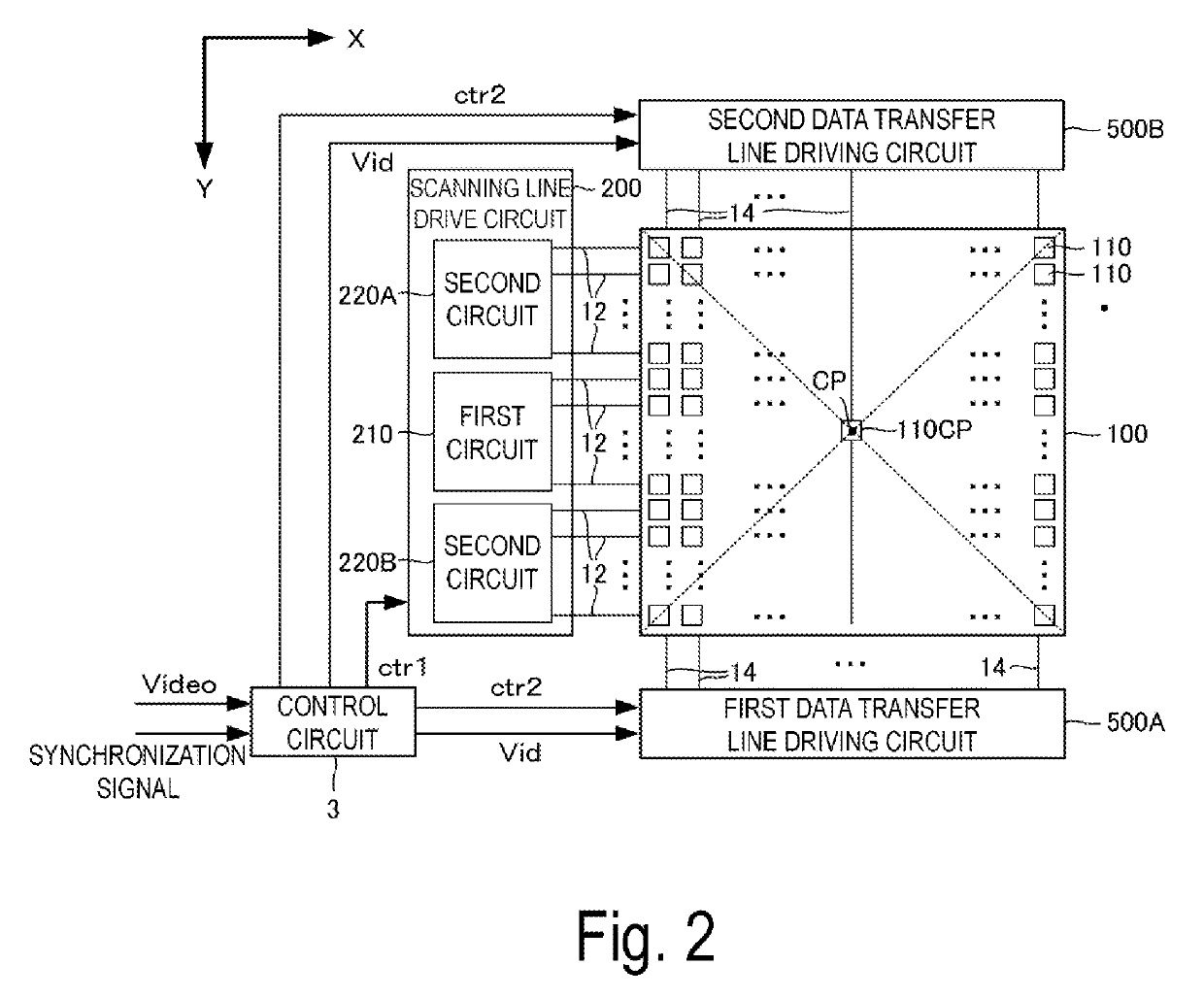
[0041]As illustrated in FIG. 1, the display device 1 includes a display panel 10. The display panel 10 includes a plurality of pixel circuits, a driving circuit for driving the pixel circuits, and a control circuit for controlling the operation of the driving circuit. In the present exemplary embodiment, the plurality of the pixel circuits, the driving circuit, and the control circuit included in the display panel 10 are formed on a silicon substrate, and an OLED which is an example of an electro-optical element is used as a light-emitting element in the pixel circuit. Further, for example, the display panel 10 is housed in a frame-shaped case 82 opened at the display unit, while being connected with one end of a Fle...

second exemplary embodiment

B. Second Exemplary Embodiment

[0067]FIG. 9 illustrates a configuration example of a display panel 10A according to Second Exemplary Embodiment of the invention. In FIG. 9, the same components as those in FIG. 2 are denoted by the same references. As is apparent from comparing FIG. 9 and FIG. 2, the display panel 10A is different from the display panel 10A in that a scanning line driving circuit 200A is provided instead of the scanning line driving circuit 200. The configuration of the scanning line driving circuit 200A is different from the configuration of the scanning line driving circuit 200 in that a second circuit 230A is provided instead of the second circuit 220A, and a second circuit 230B is provided instead of the second circuit 220B. Hereinafter, the second circuit 230A and the second circuit 230B which are different from the first exemplary embodiment will be mainly described.

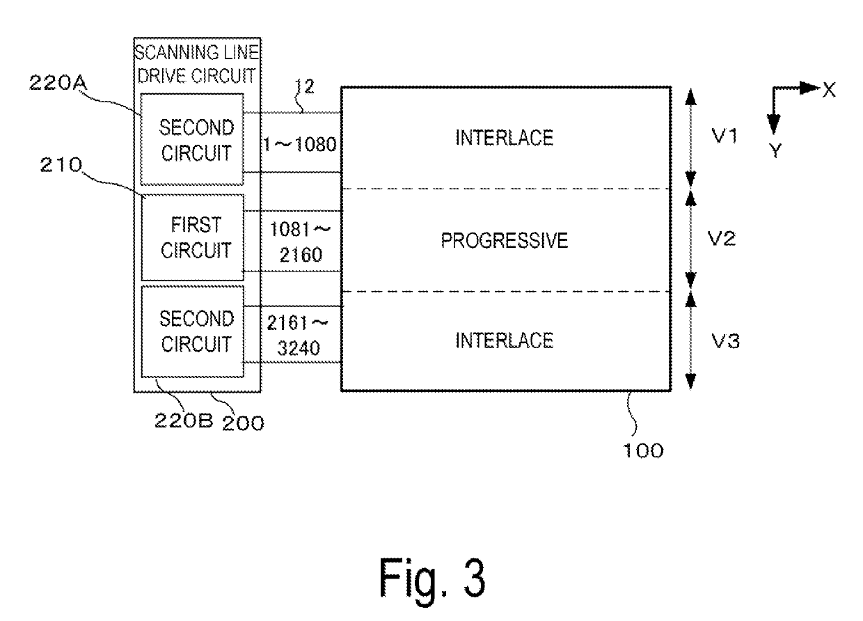
[0068]Similarly to the second circuit 220A according to First Exemplary Embodiment, 1080 scanning...

modification example

C. Modification Example

[0071]Although one exemplary embodiment of the invention has been described above, the following modification examples may be added to this exemplary embodiment.

[0072](1) In each of the pixel circuits 110 of the second circuit 220A and 220B, the scanning lines 12 may be selected every plural lines such as every two or three lines and the like during each frame period. Similarly, in each of the second circuit 230A and the second circuit 230B, the scanning lines may be selected every three or more lines. Each of the second circuits 230A and 230B may be any circuit that selects a plurality of pixel circuits 110 arranged in a matrix on the display unit 100 in units of a plurality of rows. Further, in First Exemplary Embodiment and Second Exemplary Embodiment, the same gradation signal is applied to the data transfer lines 14 of two columns adjacent to each other for the second display region, but the same gradation signal may be applied to three or more data trans...


PUM


Abstract

A display device includes a display unit including pixel circuits disposed corresponding to each intersection of plurality of scanning lines and a plurality of data transfer lines that includes a first data transfer line, a second data transfer line, and a third data transfer line, and a driving circuit configured to select the plurality of scanning lines and apply a gradation signal to the plurality of data transfer lines. The second and third data transfer lines are connected to each other.

Description

BACKGROUND1. Technical Field[0001]The invention relates to a display device and an electronic apparatus.2. Related Art[0002]A display device including a display panel in which pixel circuits including a light-emitting element such as an Organic Light-emitting Diode (OLED), transistors, and the like, are arranged in a matrix corresponding to the positions of pixels where scanning lines and data transfer lines intersect with each other has been widespread.[0003]JP-A-5-108036 discloses a display device including a plurality of display regions having different resolutions, wherein the display region closer to a central portion has higher resolution.[0004]JP-A-5-108036 does not describe a specific configuration for increasing the resolution of the display region closer to the central portion. As a general method for raising the resolution of the display panel, there is a method of increasing the number of the pixel circuits arranged in the display panel. However, there is a problem that,...

Claims


Application Information

Patent Timeline
IPC IPC(8): G09G3/3275G09G3/3266G09G3/3225
CPCG09G3/3275G09G3/3266G09G3/3225G09G2330/021G09G2300/0842G09G3/3208G09G2300/0465G09G2310/0205G09G2310/0224G09G2320/0686G09G2310/0221G09G2300/0819G09G2300/0861G09G3/3233
Inventor TAMURA, TSUYOSHIOTA, HITOSHIATSUCHI, ROBINA
Owner SEIKO EPSON CORP
Why Eureka
Try Eureka