Magnetic suspension shock absorber

a shock absorber and magnetic suspension technology, applied in the field of shock absorbers, can solve the problems of low processing precision and reduce manufacturing cost of shock absorbers, and achieve the effect of reducing manufacturing costs

Inactive Publication Date: 2019-08-01
SUHDER IND
View PDF6 Cites 5 Cited by
  • Summary
  • Abstract
  • Description
  • Claims
  • Application Information

AI Technical Summary

Benefits of technology

[0005]The magnetic suspension shock absorber of this invention is to make use of the magnetic force of the magnets of the first magnetic suspension unit and the magnets of the second magnetic suspension unit to carry out buffering of external impact and further employ the elastic member to make the magnetic suspension shock abso...

Problems solved by technology

Especially, requirements in processing precision of the magnetic suspension shock absorber are low, able to reduce manufactur...

Method used


Image

  • Magnetic suspension shock absorber
  • Magnetic suspension shock absorber
  • Magnetic suspension shock absorber

Examples


Embodiment Construction

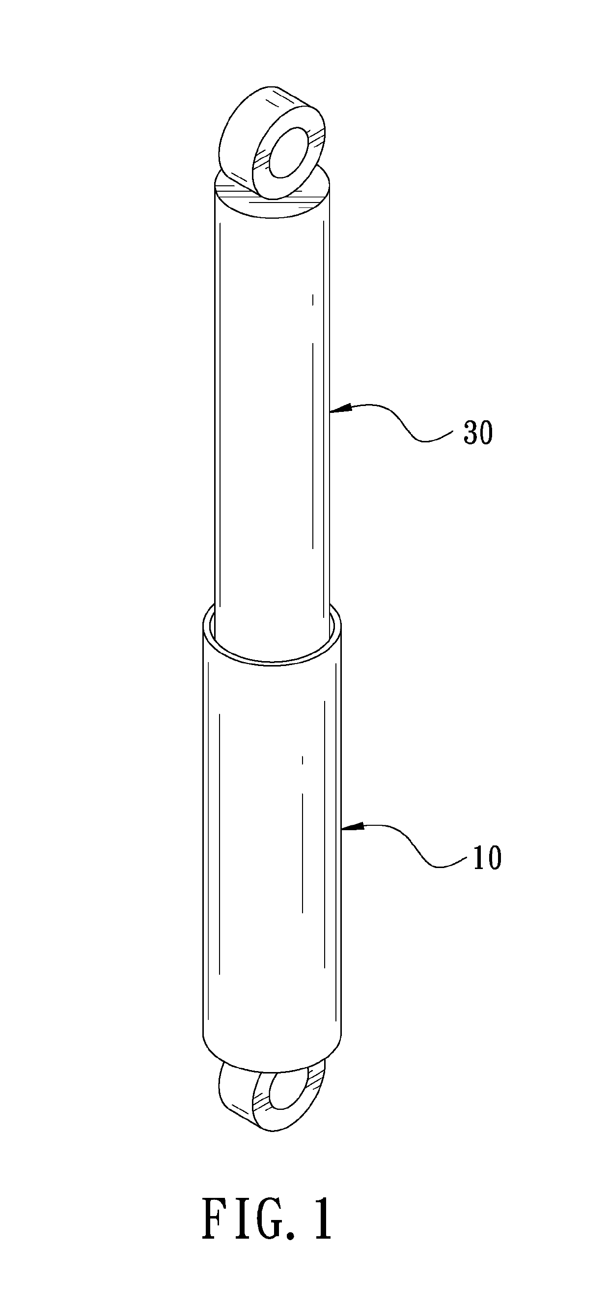
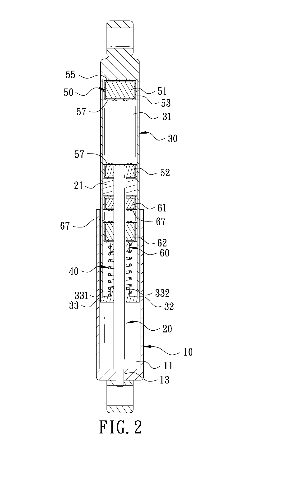
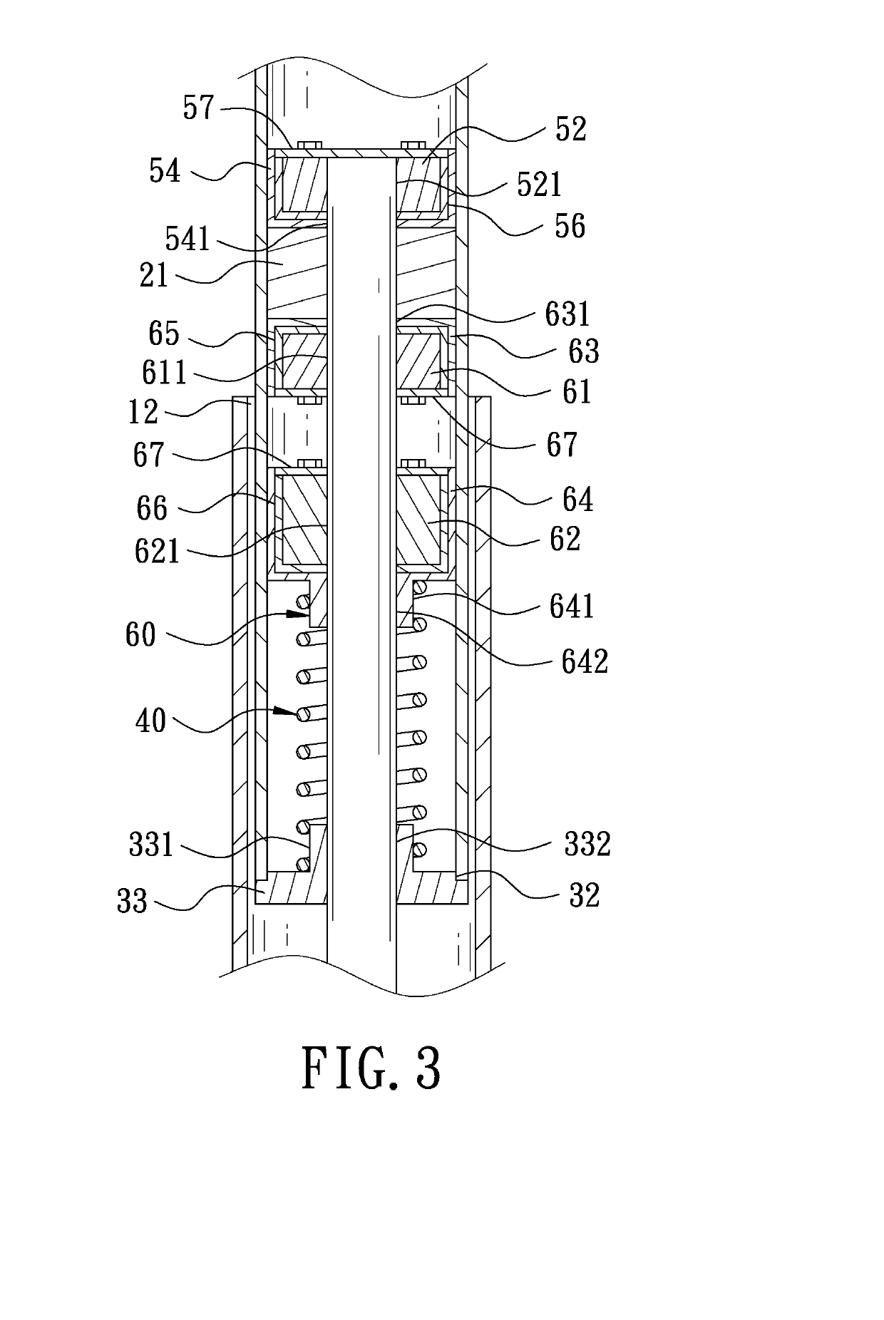
[0011]A preferred embodiment of a magnetic suspension shock absorber in the present invention, as shown in FIGS. 1-3, includes an outer telescopic cylinder 10, a shaft rod 20, an inner telescopic cylinder 30, an elastic member 40, a first magnetic suspension unit 50 and a second magnetic suspension unit 60 as main components combined together.

[0012]The outer telescopic cylinder 10 is hollow long tube-shaped, having its interior formed with an accommodating groove 11, and one end provided with an opening 12 communicating with the accommodating groove 11 and another end bored with an insert hole 13.

[0013]The shaft rod 20 has one end fixed in the insert hole 13 of the outer telescopic cylinder 10 and another end positioned in the accommodating groove 11 and inserted through the opening 12 and further provided thereon with a piston 21.

[0014]The inner telescopic cylinder 30 is combined with the shaft rod 20 and slidably fitted in the accommodating groove 11 of the outer telescopic cylind...


PUM

PropertyMeasurementUnit
Polarityaaaaaaaaaa
Circumferenceaaaaaaaaaa
Elasticityaaaaaaaaaa

Abstract

A magnetic suspension shock absorber is composed of an outer telescopic cylinder, a shaft rod, an inner telescopic cylinder and two sets of magnetic suspension units. Each set of magnetic suspension unit contains two magnets, and the corresponding surfaces of two magnets of each magnetic suspension unit are the same magnetic polarity. The magnets of two sets of magnetic suspension units are respectively combined with the outer telescopic cylinder, the shaft rod and the inner telescopic cylinder. Thus, when the inner telescopic cylinder is impacted by external force, two magnets of one magnetic suspension unit will be close to each other and produce mutual repulsion, thus achieving buffering and shock absorbing effects.

Description

BACKGROUND OF THE INVENTION1. Field of the Invention[0001]This invention relates to a shock absorber, particularly to a magnetic suspension shock absorber.2. Description of the Prior Art[0002]Conventional shock absorbers include a spring type shock absorber and a pneumatic shock absorber. The spring type shock absorber is formed with less supporting force and hence limited in application occasions and further, after frequency of use attains to a certain extent, the spring type shock absorber will result in metal fatigue and lose efficacy. The pneumatic shock absorber needs to be filled with liquid nitrogen at low temperature and has the liquid nitrogen converted into high pressure gas at normal temperature and requires high precision in processing of cylinders and pistons, complicated in manufacturing and high in cost, and further the pneumatic shock absorber may cause danger under high temperature environments and after used for a long period, the pneumatic shock absorber may lead ...

Claims


Application Information

Patent Timeline
IPC IPC(8): F16F13/00F16F15/02F16F15/03
CPCF16F13/005F16F15/022F16F15/03F16F2222/06F16F2224/0241F16F2230/0023F16F2230/10F16F6/00
Inventor BU, DER-GUEYLIU, JIA-QING
Owner SUHDER IND
Why Eureka
Try Eureka