Eureka AIR delivers breakthrough ideas for toughest innovation challenges, trusted by R&D personnel around the world.

System and method for GPS alignment using real-time kinetics

a real-time kinetic and alignment system technology, applied in vehicle position/course/altitude control, process and machine control, instruments, etc., can solve problems such as mechanical and electrical breakdowns, mechanical breakdowns, and mechanical breakdowns of modern irrigation machines, and achieve the effect of reducing distan

Active Publication Date: 2019-08-01
VALMONT INDUSTIES INC
View PDF0 Cites 10 Cited by
  • Summary
  • Abstract
  • Description
  • Claims
  • Application Information

AI Technical Summary

Benefits of technology

The present invention provides a method for correcting GPS location data using RTK error data. The method includes steps of comparing GPS location data with RTK error data, calculating RTK error correction data, transmitting the data to intermediate and last drive towers, calculating the location of the last drive tower, calculating a straight, center line between the center pivot and the last drive unit, calculating the relative distances between each intermediate drive tower and the calculated center line, and controlling the average speed over time of each intermediate drive tower to reduce distance between their current locations the calculated center line. The technical effect of the invention is to improve the accuracy of GPS location data in precision agricultural applications.

Problems solved by technology

Given their size and complexity, modern irrigation machines are prone to repeated mechanical and electrical breakdowns.
One important source of mechanical breakdowns is misalignment of drive towers.
These systems have large response times and lack the ability to fine-tune alignment changes.
As such they are susceptible to changes in span orientation (span roll) due to wind, terrain or the like.
Further these systems utilize a fairly wide alignment error band before a motor is started or stopped, typically on the order of ±1.5 degrees misalignment, thus causing the high structural stresses discussed above.
These systems are prone to slow response times due to the transmission lags.
Further, GPS based systems without sonic type of correction (such as RTK, WARS, D-GPS, or the like) all suffer from a significant margin of error which is generally too large to be useful when fine tuning the alignment of irrigation spans.

Method used


Image

  • System and method for GPS alignment using real-time kinetics
  • System and method for GPS alignment using real-time kinetics
  • System and method for GPS alignment using real-time kinetics

Examples


Embodiment Construction

[0018]For the purposes of promoting an understanding of the principles of the present invention, reference will now be made to the embodiments illustrated in the drawings and specific language will be used to describe the same. It will nevertheless be understood that no limitation of the scope of the present invention is hereby intended and such alterations and further modifications in the illustrated devices are contemplated as would normally occur to one skilled in the art.

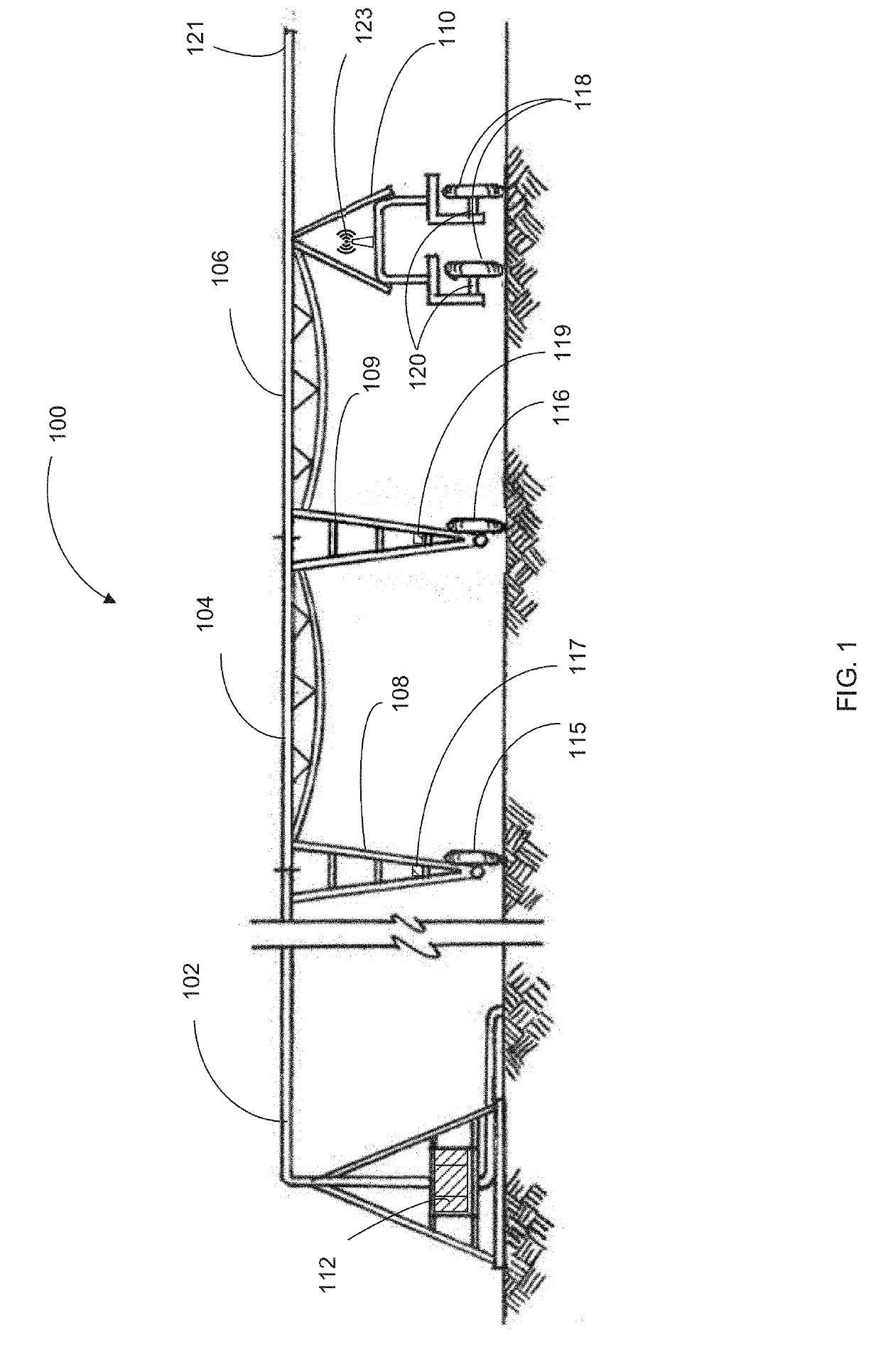
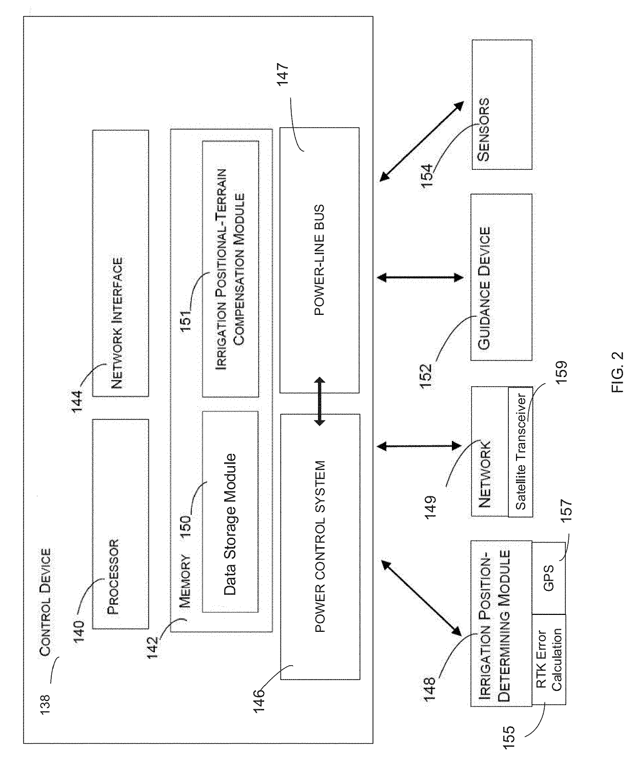
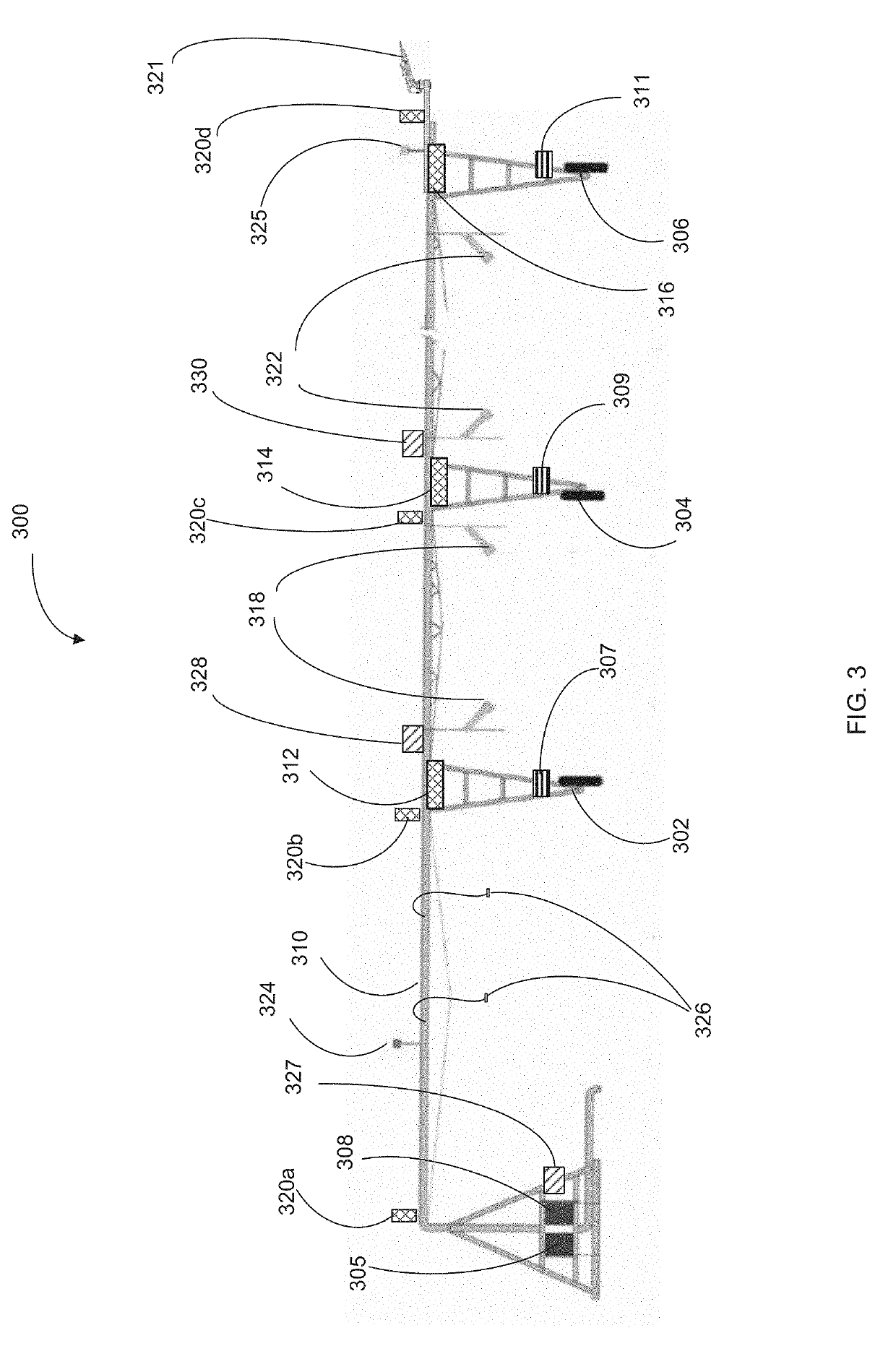
[0019]In accordance with preferred embodiments of the present invention, it should be understood that the term “drive unit” may preferably include a number of sub-components including: a motor, a controller, a communication device (such as a PLC or the like) and an alignment device. Further, while the invention is discussed below respect to three exemplary towers, the number of towers used may be expanded or reduced (i.e. 2-100 towers as needed without departing from the spirit of the present invention. Further,...


PUM


Abstract

The present invention provides a system for aligning drive towers within an irrigation system. According to a preferred embodiment, the present invention relates generally to a system and method for alignment control of irrigation spans and, more particularly, to a system and method for GPS alignment of irrigation spans using real-time kinetics sent via power line carrier.

Description

RELATED APPLICATIONS[0001]The present application claims priority to U.S. Provisional Application No. 62 / 623,587 filed Jan. 30, 2018.BACKGROUND AND FIELD OF THE PRESENT INVENTIONField of the Present invention[0002]The present invention relates generally to a system and method for alignment control of irrigation spans and, more particularly, to a system and method for GPS alignment of irrigation spans using real-time kinetics sent via power line carrier.Background of the Invention[0003]Modern center pivot and linear irrigation systems generally include interconnected spans (e.g., irrigation spans) supported by one or more tower structures to support the conduits (e.g., water pipe sections). In turn, the conduits are further attached to sprinkler / nozzle systems which spray water (or other applicants) in a desired pattern. In these modern irrigation systems, a significant number of powered elements are used to control various aspects of irrigation. These often include remote, independe...

Claims


Application Information

Patent Timeline
IPC IPC(8): G01S19/43G05D1/02G01S19/51A01G25/09
CPCG01S19/43G05D1/0219G01S19/51A01G25/092G05D1/0278G05D1/028G05D2201/0201G01S19/14
Inventor THATCHER, TRACY A.
Owner VALMONT INDUSTIES INC
Why Eureka
Eureka Blog
Learn More