
Neural Stimulation for Reduced Artefact

a technology of artefact and neural stimulation, applied in the field of neural stimulation, can solve the problems of difficult task, significant obstacle to isolating or even detecting the much smaller cap signal of interest, impracticality of implant system, etc., and achieve the effect of improving the observation of the evoked neural respons

Active Publication Date: 2019-08-08
SALUDA MEDICAL
View PDF0 Cites 27 Cited by
  • Summary
  • Abstract
  • Description
  • Claims
  • Application Information

AI Technical Summary

Benefits of technology

This patent recognizes that adjusting the ratio between two charges can make an artificial vector perpendicular to the natural response vector, which results in an improved detection of the evoked neural response.

Problems solved by technology

However, this can be a difficult task as an observed CAP signal component in the neural measurement will typically have a maximum amplitude in the range of microvolts.
In contrast a stimulus applied to evoke the CAP is typically several volts and results in electrode artefact, which manifests in the neural measurement as a decaying output of several millivolts partly or wholly contemporaneously with the CAP signal, presenting a significant obstacle to isolating or even detecting the much smaller CAP signal of interest.
For example, to resolve a 10 μV CAP with 1 μV resolution in the presence of an input 5 V stimulus, for example, requires an amplifier with a dynamic range of 134 dB, which is impractical in implant systems.
As the neural response can be contemporaneous with the stimulus and / or the stimulus artefact, CAP measurements present a difficult challenge of measurement amplifier design.
In practice, many non-ideal aspects of a circuit lead to artefact, and as these mostly have a decaying exponential appearance that can be of positive or negative polarity, their identification and elimination can be laborious.
The difficulty of this problem is further exacerbated when attempting to implement CAP detection in an implanted device.
Daly (U.S. Pat. No. 8,454,529) suggests application of a stimulus, followed by a compensatory pulse, however Daly's biphasic stimulus and compensatory pulse together are not charge balanced and thus cause a net charge transfer between the device and the tissue.

Method used


Image

  • Neural Stimulation for Reduced Artefact
  • Neural Stimulation for Reduced Artefact
  • Neural Stimulation for Reduced Artefact

Examples


first embodiment

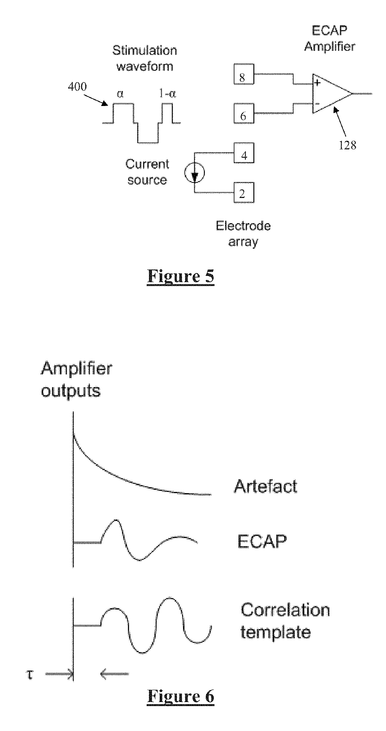
[0073]FIG. 5 schematically illustrates delivery of the stimulus 400 to the neural tissue. In a first embodiment, neural response signals observed by electrodes 6 and 8 are processed by the controller 116 using a dot-product detector, in the manner disclosed in the present applicant's International Patent Publication No. WO2015074121, the content of which is incorporated herein by reference. Beneficially, such embodiments recognise that a dot product detector produces an output that can be positive or negative depending in the relative phase of the artefact and the detector. As shown in FIGS. 6 and 7, and described more fully in WO2015074121 in relation to FIG. 7 of that publication in particular, varying a detector time delay τ influences a phase angle of the observed neural response vector. The present invention further recognises that varying the duty ratio a of stimulus 400 influences the phase angle of the artefact as measured by the detector output. The parameters τ and α thus ...

second embodiment

[0075]In a second embodiment, the neural response signals observed by electrodes 6 and 8 are processed by the controller 116 using peak-to-peak detection. A peak-to-peak detector can only produce a positive value for the artefact. FIG. 9 shows the peak-to-peak artefact for tri-phasic stimulation as a function of the ratio of the first and third pulses. Again, observations were made for four different sense electrodes of the array to produce the four traces of FIG. 9.

[0076]When compared to a biphasic waveform, which has a 0% duty cycle (α=0), extrapolating the graph of FIG. 9 would be expected to give artefact of at least 40 μV. Thus, the variable duty-cycle tri-phasic stimulation produces a trough through the range 0.2<α<0.7), which may be of assistance in some scenarios. However this trough is only a few dB lower than the peak value and so of lesser value than the embodiment of FIG. 8.

[0077]A further particular advantage of some embodiments of the present invention is that the para...


PUM


Abstract

A neural stimulus comprises at least three stimulus components, each comprising at least one of a temporal stimulus phase and a spatial stimulus pole. A first stimulus component delivers a first charge which is unequal to a third charge delivered by a third stimulus component, and the first charge and third charge are selected so as to give rise to reduced artefact at recording electrodes. In turn this may be exploited to independently control a correlation delay of a vector detector and an artefact vector to be non-parallel or orthogonal.

Description

CROSS-REFERENCE TO RELATED APPLICATIONS[0001]This application claims the benefit of Australian Provisional Patent Application No. 2016902492 filed 24 Jun. 2016, which is incorporated herein by reference.TECHNICAL FIELD[0002]The present invention relates to neural stimulation, and in particular to a method and device configured to deliver a neural stimulus in a manner to give rise to reduced amounts of artefact so as to ease the task of recording a neural response evoked by the neural stimulus.BACKGROUND OF THE INVENTION[0003]Electrical neuromodulation is used or envisaged for use to treat a variety of disorders including chronic pain, Parkinson's disease, and migraine, and to restore function such as hearing and motor function. A neuromodulation system applies an electrical pulse to neural tissue in order to generate a therapeutic effect. Such a system typically comprises an implanted electrical pulse generator, and a power source such as a battery that may be rechargeable by transc...

Claims


Application Information

Patent Timeline
IPC IPC(8): A61B5/0484A61B5/0478A61B5/00
CPCA61B5/0484A61B5/0478A61B5/7225A61B2562/063A61B5/686A61B5/05A61N1/37264A61N1/3787A61N1/36067A61N1/36071A61N1/36075A61B5/24A61N1/36A61N1/18A61B5/377A61B5/291
Inventor KARANTONIS, DEANSINGLE, PETER SCOTT VALLACKHUANG, KAI
Owner SALUDA MEDICAL
Learn More